In this short tutorial, we will show you how you can build yourself a transistor-driven color-changing RGB LED lights. The building process is simple and requires only a few transistors, capacitors and resistors to build it. The lighting system built in this way is not only efficient but cost effective but it can also create stunning color effects that can transform any room.
RGB LED Pinout
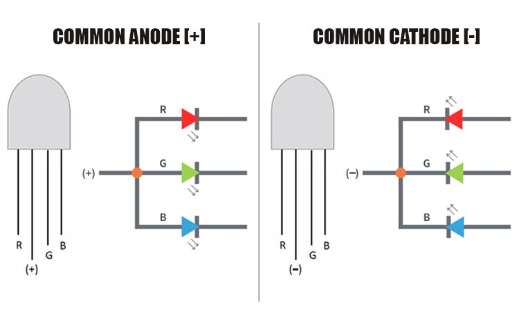
The pinout of the common anode and common cathode RGB LEDs are shown below.
There are two types of LEDs common anode and common cathode and for this project, we will be using common anode LEDs. The common Anode LEDs have RGB in common and
Pin R The negative terminal of the common Anode LED or the positive terminal of the common cathode LED depending upon the common Anode or common Cathode configuration. Connecting it to Ground or VCC will light up the LED Red.
Pin G Connect the G pin to Ground in case of common Anode LED. Connect the G Pin to VCC in case of a common cathode LED. doing so will light the LED Green.
Pin B In case of a common Anode LED connecting the B pin to Ground will light up the LED. and if the LED is a common cathode, connecting it to VCC will light up the LED.
+/- Pin The (+) and (-) pins represent the common cathode or common Anode Pins of the LED. For a common anode LED connect this pin to VCC, for common cathode LED it should be connected to the ground.
Components Required to Build LED Tree
Components required to build the RGB LED Tree are simple and can be found in your local hobby store
Common Anode RGB LED - 10
470uF Capacitor - 3
82K Resistor - 3
BD140 Transistor - 3
Perf Board
Soldering Wire
Jumper Wires
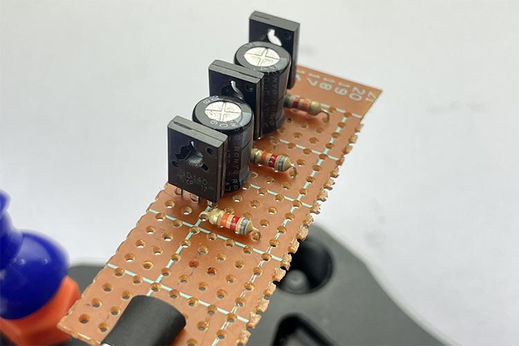
Circuit Diagram - Color Changing RGB LED Tree
The complete schematic diagram of the color changing RGB LED Tree is shown below the circuit is very simple and easy to understand. The LEDs that we have used in the circuit are all common Anode LEDs, and all of them are connected in parallel. The working of the driver circuit is also very simple,
when power is applied to the circuit the capacitor at the base of the transistor starts charging, and after a certain period of time it will reach a threshold where the transistor will completely turn on and the LEDs corresponding to that channel will light up,
Now as current flows through the first transistor the capacitor to the next transistor starts charging and after a certain period of time the next transistor turns on and the LEDs corresponding to that transistor turns ON and the process repeats for the next set of LEDs. This is how the R, G, and B LEDs change colors.
If you want to control some RGB LED lights with ESP8266 and Wi-Fi then this project is for you because in this project we have made a simple circuit to do so.
If you are looking for some cool, interesting and funkey project online which will make you stand out in a party then this project is for you, because in this project we have built DIY RGB LED glasses which can also display visual effects.
If you love spectrum analyzers like me then this project is for you because in this project we have made a DIY! Music spectrum analyzer with ARM microcontroller and Keil IDE.
Looking for a cool little night lamp on the internet, then this project is for you, because in this project we have made a cool little Android operated night lamp with Blunk app and ESP8266 microcontroller.
A month back, around 5.9 million tonnes of Lithium have been discovered in the state of Jammu and Kashmir for the first time, claimed by the union government. But, experts on the other hand stated that Lithium reserves were already discovered in the state back in 1999. Lithium, often known as the ‘White Gold’ is now a very important mineral as it is mostly utilized in the manufacturing process of batteries. And because of their higher density they are used in smartphones, electric vehicles, and other electronic devices. India now stands as the sixth biggest known reserves of Lithium resources in the globe. As per the official statement of the central government, out of thee 51 mineral blocks, 5 blocks pertains to gold and other blocks pertains to commodities like potash, molybdenum, base metals etc. spread across 11 states of Jammu & Kashmir (UT), Andhra Pradesh, Chhattisgarh, Gujarat, Jharkhand, Karnataka, Madhya Pradesh, Odisha, Rajasthan, Tamil Nadu and Telangana.
Now, India is undertaking various efforts to boost the growth of the electric vehicle industry and also trying to make it affordable for the people. Some experts and government officials believe that this massive discovery of Lithium will provide impetus to the manufacturing of EV battery cells. In order to uplift the growth of lithium-ion battery manufacturing, India requires Rs 33,750 crore of investment, reports Council on Energy, Environment and Water (CEEW). By the end of 2030, the country’s lithium battery production is anticipated to be around 70-100 GWh. According to automobile experts of the country, the discovery seems very optimistic for the future of the EV industry. In this regard, Sohinder Gill, Director General, SMEV and CEO at Hero Electric told CircuitDigest, "We applaud the government's efforts in finding an Indian lithium resource. It's a big step forward for the nation. Only a few nations now supply lithium for the production of batteries. Lithium accounts for ~15% of the battery's cost. The cost of batteries could drop by 5% if we can purchase lithium from the Indian reserve for a price that is 2/3rd of the cost of the imported material, making EVs more affordable. The EV sector will become "Atmanirbhar" and the control of Chinese firms over the raw material will be further diminished if we are able to obtain the lithium in sufficient quantities from Indian deposits."
Since lithium is a major component in batteries, its discovery in J&K will help India progress at a faster pace in the field of battery manufacturing for the automotive industry and consumer electronics. According to a Counterpoint Research survey, the global energy storage demand for just passenger EVs is expected to reach over 3.8TWh by 2030. Along with the demand from CVs and renewable energy storage like solar and wind, the total energy storage demand for 2030 will reach a much higher number. Although other battery chemistries are being developed, as of now lithium batteries are the most reliable for energy storage. China, Europe and the US all are racing to set up battery manufacturing plants. The recently discovered lithium deposits will help India strengthen its position in the global energy market.
India’s Current Lithium Mining Scenario and Possible Challenges
As of 2022, India was importing battery cells for battery pack assembly mostly from China. According to the Ministry of Commerce and Industries, India imported Rs 163 billion worth of lithium and lithium-ion between April and December 2022. In 2022, India cleared a budget of Rs 18,100 crore to set up 50GWh of ACC manufacturing capacity by 2030 under the PLI scheme. The ACC PLI is expected to boost India’s EV adoption and strengthen India’s position in the energy market as well. EV sales in India are expected to reach 65% of total vehicle sales or over 24.5 million units by 2030. In an exclusive interaction with CircuitDigest, Abhik Mukherjee, Research Analyst at Counterpoint told, "the discovery of lithium along with the 2023 budget announcement of reduced excise duty on machinery required for manufacturing lithium-ion batteries will help India achieve its EV and energy generation targets at a much lower cost. It will reduce import dependency, new battery manufacturing plants will be set up, the mining sector will experience a boom and new job creation will be witnessed.”
The Salal-Himalaya region where the deposit has been found is a geographically very delicate region. It is being feared that the earthquake-prone area will face ecological destruction if heavy mining activities are carried out. Moreover, lithium extraction is a water-intensive process. Nearly 2 million liters of water is required to extract just 1 tonne of lithium. This will put huge pressure on the region’s ecosystem. Experts are suggesting ways for sustainable mining, but the higher cost of sustainable mining will reduce revenue and profits. Currently, India does not possess the technology for lithium extraction. “As India allows 100% foreign investment in the mining sector, it is expected that foreign companies will be given the responsibility of lithium extraction initially, which is not favorable for the domestic mining sector. But from a long-term perspective, we expect India to benefit from the technology transfer. Alongside these hardships, the threats from radical groups operating in and around the J&K region are something that the government needs to neutralize before the mining begins,” added Abhik. The project has the potential to face a lot of heat from locals, climate activists and radical groups, and the government will have to work its way around these hardships for a greener future.
The Geological Survey of India (GSI) experts noted that it is the time to view and scrutinize how much of the discovered lithium is viable and feasible and can be commercially extracted. More examination will actually discover the volume of the total reserve. China on the other hand has already unleashed top-notch infrastructure and technological equipment and their years of experience of lithium mining extraction and refinery is an added advantage. India requires more government assistance, investment, and energy. Also, India lacks experience in refining lithium because it is associated with rocks and other minerals. The rocks need to be broken and wiping out certain chemicals with evaporation and also magnetic contamination with magnets. India has no experience in doing all these activities and moreover, there is no trusted technology, machineries and industries associated with this.
Speaking about the grave challenges of extracting Lithium in India, Senior Geologist and Earth Scientist Dr. Sreedhar Ramamurthy told CircuitDigest exclusively, "There is huge euphoria over the reported 5.9 Million Tonnes of "inferred" lithium ore near Salal in J&K based on the preliminary survey by GSI. GSI has earlier reported finds of Lithium in Karnataka, but this has attracted a lot of attention. The actual quantity of Lithium ore and extractable amount would be only known after detailed exploration is undertaken. Generally Lithium content is less than 2% of the ore. The technology to extract Lithium has to be sourced. Being in a fragile ecosystem of the Himalayas, it's also a major concern as to how mining would adversely affect the local environment. It's also worth noting that EVs could be some relief to the polluted urban environments but they fundamentally seem to be yet another 'false-solution' to the larger issue of climate justice."
Although the discovered Lithium is likely to uplift the growth of EVs in India, experts have clearly stated that if the resource is not mined scientifically then there could be serious environmental depletion and it could pose serious risks of soil degradation and air pollution. On the other hand, the waste disposal, refining, and open cast mining contaminates the groundwater largely thereby disturbing the biodiversity. The extraction from the ore is mostly water-intensive, around 2.2 million liters of water will be wasted for extracting one tonne of lithium. Additionally, mining in the Himalayan region has various societal impacts and could displace the local communities, explain experts. This particular region is home to a huge number of indigenous communities and the government could face fierce activism over this issue if mining begins.
Conclusion and Possible Solution
Back in May 2021, the central government announced a PLI scheme of Rs 18,100 crore for a term of five years to manufacture Advance Chemistry Cells (ACC) in the nation. In the same year in June, there were three bidders such as Reliance New Energy Limited who signed the agreement under the PLI scheme. Most importantly, as there are no possible alternatives, the country will have to carry on importing because there are deadlines for various ventures aimed at zero-carbon emissions coming near. Also, during the 26th United Nations Climate Change Conference of the Parties (COP26) in Glasgow in 2021, India assured to reduce emissions to net-zero by the end of 2070 and therefore, the discovery of lithium would be critical to meet the targets in the coming years.
According to a report by the International Energy Agency (IEA), there could be lithium shortages internationally towards the end of 2025 and by 2050 around 2 billion electric vehicles are required to meet the net-zero target. But, EV's sales reached only 6.6 million globally. The supply of lithium is facing hurdles not only from the augmenting demand, but the resources are concentrated in few places and most of its production is available in regions with vast water stress.
Speaking of the growth and possible solution, Rajoo Goel, Secretary General of industry body ELCINA said, “Discovery of Lithium reserves in J&K is a very significant and positive development for India. It is an invaluable resource and will strengthen and accelerate the development of EV's and renewable energy capacity in India. It will enhance energy storage capacity and reduce use of fossil fuels. The key to success of course lies in successfully mining and processing Lithium for industrial use. Lithium ion batteries are a key component for energizing electronic equipment and transportation systems. We however, need to ensure safe use and recycling of Lithium based products to protect the environment.”
It is arguable that a significant contributing factor to the success of Arduino, especially in its earliest days, was the cottage industry of complementary boards created and sold by third parties. These boards, known as shields, could be inserted into the unique headers of the Arduino form factor found onboard the Diecimila, Duemilanove, and current generation Uno boards. They helped to expand the functionality of the underlying Arduino board by allowing designers to quickly integrate a variety of sensors and actuators into their Arduino-based projects. The interoperability and the ability to nest multiple shields proved a decisive victory for Arduino. Indeed, today many other embedded system manufacturers offer development boards that feature compatibility with Arduino shields (Figure 1).
Figure 1: Shields enable customized, modular design on top of the core Arduino development boards. (Source: Mouser Electronics)
The popularity of the original Arduino form factor did not prevent the company from introducing a variety of additional form factors that retained the ease of tinkering and programming. The electronics at the heart of the Arduino board have evolved over the years. Newer microcontrollers have been incorporated to provide more processing horsepower. Over the years, hardware has been added to provide increased functionality, such as Wi-Fi® and BLUETOOTH® wireless communications. Arduino has even released technology and curriculum bundles aimed at teaching science and robotics courses. Some of the highlights from the years of hardware evolution are:
Mega: Physically a much larger board than the Uno that exposed significantly more I/O pins (the current revision has 54 digital I/O pins, 16 analog inputs, and 4 UARTs) to give the designer more flexibility and to create more complex systems (Figure 2).
Figure 2: The Arduino Mega. (Source: Mouser Electronics)
Micro and Nano: As their names imply, Micro and Nano form factors are much smaller than the Uno form factor. The smaller form factor made them preferable for final designs or applications with significant size restraints.
Lilypad: Explicitly created for those with an interest in wearable electronics. Conductive thread replaces traditional wire as the means of connecting components.
MKR: The MKR line of boards is arguably the first attempt of Arduino to bridge the maker and professional markets. While the MKR family shares a compact common form factor, it offers a wide variety of architectures, communications protocols, shield-based sensors, actuators, and system interfaces. For example, there are MKR boards with Wi-Fi, LoRa, and GSM wireless protocols. In addition, there are shields for interacting with DC motors, CANbus, and RS–485 industrial protocols.
Figure 3: An example of the Arduino MKR form factor. (Source: Mouser Electronics)
VIDOR 4000: The VIDOR was Arduino’s first attempt at Field Programmable Gate Array (FPGA) hardware versus microcontrollers. While the VIDOR shared the same Cortex-M0 32-bit SAMD21 as other MKR boards and was thus programmable via the Arduino IDE, the FPGA-side of the board never really fulfilled the promise of bringing hardware description languages (HDL) such as Verilog and VHDL to the masses. Though using industrial-strength tools, it is possible to program the VIDOR with HDL; it has never proven to be something that most makers (or even professionals) have really tried to attempt.
Portenta: The Portena line of embedded system products marked Arduino’s expansion into hardware for dedicated professional development. Portenta brings numerous hardware improvements that make it preferable for industrial applications such as factories and automobiles. In addition, built-in support for wireless protocols such as Wi-Fi, BLE, LoRa, LTE Cat-M, and NB-IoT and legacy wired protocols such as RS-485 means Arduino can help bridge the gap between the old and the new, ensuring reliability while also adding new functionality such as machine learning and digital twins. Furthermore, the seeds of Arduino’s investment in the education market will sow countless rewards as young people who learned about electronics using an Arduino Uno will have less of a learning curve with the newer professional-grade Arduino products.
Nicla: The Nicla also falls under the professional umbrella, with the Nicla Vision focusing on AI-based computer vision applications (Figure 4). The almost stamp-sized form factor with the built-in camera means the Nicla Vision can be easily integrated into existing machinery with minimum fuss. The Nicla Sense ME has the same form factor while providing professional-grade motion and environmental sensing capability.
Figure 4: The Nicla Vision is offered as an AI-powered machine vision dev board. (Source: Mouser Electronics)
In the late 2010s, Arduino made moves to expand from just a hardware manufacturer to a full-fledged embedded systems ecosystem. 2019 saw the release of an online test-based certification program that allowed individuals to prove their knowledge of basic electronics, software development, and certain aspects of the Arduino ecosystem. Then in September 2020, Arduino took ownership of Google’s Science Journal smartphone application used in many science curricula (Figure 5). They even expanded the app's capability to use not just the onboard smartphone sensors but also sensors found aboard the Arduino Nano 33 BLE Sense development board.
Figure 5: The Arduino Science Lab app makes visualizing sensor data a snap. (Source: Arduino)
Arduino Today, Arduino Tomorrow
As we find ourselves rapidly approaching the beginning of Arduinos third decade, it is pretty remarkable to look back at the growth of an ecosystem that has already revolutionized electronics education and is well-positioned to do much more in the future. Today Arduino is much more than an artist-designed 8-bit microcontroller-based circuit board and barebones software development environment. Indeed, they are keeping pace, if not leading the charge, in moving embedded systems technology into the future.
There are two major trends that embedded systems developers must continue to appreciate and invest in if they wish to remain competitive. The first is the push of AI technology (such as machine learning) to the “edge,” meaning embedded electronics right at the point of action, far removed from relying on high-end servers to do all the computationally intensive processing. The Portenta and Nicla products mentioned earlier, along with partnerships with companies such as Edge Impulse, show that Arduino has no intention of resting on its laurels and is embracing AI technology.
The second trend is the continuing incremental rollout of the Internet of Things and the recent emergence of technologies explicitly built for IoT, such as Thread. In recent years, Arduino embraced the cloud and IoT (Figure 6). Starting as Arudino Create before being rebranded as Arduino Cloud in 2021, the hosted service gives developers a convenient cloud-based platform to remotely monitor and control Arduino-based solutions. Arduino made this even more convenient with the release of their IoT Remote smartphone applications available for both iOS and Android.
Figure 6: The Arduino IoT Cloud provides an entire ecosystem to manage, view, and remotely control internet-connected devices. (Source: Green Shoe Garage)
The future is looking bright for Arduino. In the course of researching and writing this article, additional significant announcements were made regarding future Arduino hardware and services. First, the company just announced Opta, their first-ever Programmable Logic Controller (PLC) for industrial applications (Figure 7). The Opta will be programmable using industry-standard ladder logic diagrams and function block diagrams. Additionally, the company announced Arduino Cloud for Business. In a way that mirrors how the Pro line of products moved Arduino into industrial-grade hardware, Arduino Cloud for Business will transform Arduino Cloud in a similar manner. In addition, the business offering will include features that will make Arduino-based edge devices easier to securely provision, monitor, and update at scale.
Figure 7: The Arduino Opta, Arduino’s first PLC. (Source: Arduino)
Happy 20th Birthday, Arduino!
2023 marks Arduino’s 20th year of existence. So much has changed in our world in the intervening years. Then, there were no iPhones or Android devices, Netflix was a company that sent you DVDs via snail mail, and embedded systems were the purview of large corporations and the most tenacious hobbyists. Today we live in a world where almost anyone interested in electronics can get involved in a very hands-on way. And while Arduino is not the only company to help create this modern world, it certainly casts a big shadow for a small company started by five people at a small academic institution in Ivrea, Italy. So here is to the next twenty years, Arduino.
Michael Parks, P.E. is the co-founder of Green Shoe Garage, a custom electronics design studio and embedded security research firm located in Western Maryland. He produces the Gears of Resistance Podcast to help raise public awareness of technical and scientific matters. Michael is also a licensed Professional Engineer in the state of Maryland and holds a Master’s degree in systems engineering from Johns Hopkins University.
The automobile industry during the time of the COVID-19 pandemic has been facing numerous impediments such as the escalation of electric mobility, ridesharing, and the volume of production of cars came to a halt. During that time, global analysts have mentioned that this particular sector would be facing more intricate challenges to regain its growth and momentum like the pre-pandemic level. In the UK alone, the automotive industry contributes more than £15 billion to the economy and turns over nearly £79 billion annually.
The Internet of Things (IoT) industry has been growing tremendously since the last couple of years and it has now become an imperative part of human’s lives and also for business and communication. Speaking of globally, there are 14.4 billion devices where there are almost two IoT devices for every person on the planet. According to the experts, by the end of 2050, there will be 24 billion IoT devices all over the world.
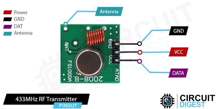
When it comes to giving your projects wireless capabilities, A 433MHz RF Module is the most common and easiest way to get things done. A 433MHz RF module uses the ASK modulation methods to transmit and receive data between two devices. It is widely used in many applications, including remote control systems, wireless security systems, and telemetry systems. So in this tutorial, we will make a simple circuit with the help of the 433 Mhz RF module that requires no microcontroller and no code to light an LED wireless.
Note: If we search the web for 433MHz RF modules, you will find many different variations of this module, but only the green module with variable capacitor works, at least from what we have tested.
433Mhz RF Module Pinout
DATA Pin accepts digital data that's needed to be transmitted.
VCC is the power pin of the module. The operating voltage of the device is 3.3V to 5V. Please note that the range of the device is directly proportional to the supply voltage. This means providing more voltage can provide it with more range.
GND is the Ground pin of the RF Transmitter module.
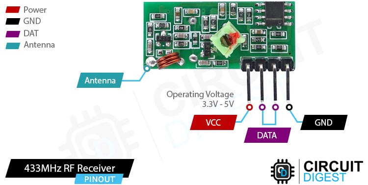
VCC Provides power to the 433MHz module. Unlike the transmitter, the receiver requires a 3.3V - 5V supply voltage.
DATA There are two data pins for the module This is the data out pin of the module.
GND The first ground pin of the module.
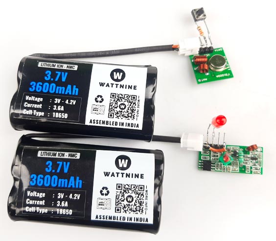
Circuit Diagram of 433MHz RF Transceiver
The schematic diagram of the RF link is shown below, the circuit is very simple and can be built very easily.
At the left hand side we can see the 433MHz RF Receiver and on the right hand side we can see the RF Transmitter. In the transmitter we have connected a push button with a resistor in series and, for the receiver we have connected a LED on the Data line, and both the circuits are powered by a 3.7V lithium battery pack. The Image shown below shows the complete circuit of the 433MHz RF Tx RX module in working state.
If you are thinking about building a wireless doorbell, then this is the project that you are looking for. In this project we have built a Doorbell using 433MHz RF links and Arduino.
If you are trying to build a simple RF based wireless switch, then this project is for you. In this project we have used the HT12E and HT12D encoder decoder module to light up some LEDs.
If you are looking for a simple home automation project then this might be the one you are looking for, as in this project we have used some RF modules and relays to enable and disable a CFL lamp.
If you want to learn in depth about the working of a 433MHz RF link then you definitely need to check this project, because in this project we have gone into details about the 433Mhz RF link and interfaced a ESP32 with it as an example.
The Italian Renaissance was an incredible two-hundred-year period of human history marked by remarkable advancement in both the arts as well as science and technology. Names like Leonardo da Vinci, Galileo Galilei, and Sandro Botticelli are but a few of the great minds that gifted the world with incredible knowledge, art, and inventions (Figure 1). A few centuries later, a renaissance in electronics would emerge from a small town in Italy named Ivrea. And it all began with a hand-soldered circuit board that would become known globally as Arduino.
Figure 1: Da Vinci's "Mona Lisa" shows the convergence of science and art during the Renaissance period. (Source: By Leonardo da Vinci - Cropped and relevelled from File:Mona Lisa, by Leonardo da Vinci, from C2RMF.jpg. Originally C2RMF: Galerie de tableaux en très haute définition: image page, Public Domain. From Wikimedia Commons)
In the (Academic) Beginning…
Before the early 2000s, many engineers and makers interested in embedded electronics cut their teeth on the PIC-based BASIC Stamp platform. BASIC Stamp became popular since the hardware was relatively inexpensive compared to most microcontroller platforms of the time. $139USD (inflation-adjusted to 2022, almost $400) in the 1990s got you a Stamp, parallel port programming cable, and a copy of Stamp Editor. The BASIC-esque programming language (a variant named PBASIC) was easy to learn, but the editor only ran on Windows. Still, the emphasis of BASIC Stamp was on those with a technical mindset. For many of those with an artistic bent who yearned for a way to integrate technology into their art, the BASIC Stamp proved to be less than ideal as it was not programmable on a Mac, and the cost was still a bit high, especially for students.
Around 2003 this would begin to change. Enter the Interaction Design Institute Ivrea (IDII) and a perfect storm of technology and art (Figure 2).
Figure 2: Interaction Design Institute Ivrea (IDII), the birthplace of Arduino. (Source: Arduino)
A group of students and professors whose work revolved around interactive art were frustrated that the technology of the time was more a hindrance than a help in bringing their creative works to life. Some of the earliest people involved were Hernando Barragán, Massimo Banzi, Casey Reas, and Ben Fry. Barragán’s master's thesis was the Wiring development platform built around the humble ATmega128 microcontroller and a handmade circuit board. Banzi was one of Barragán’s advisors along with Reas. Fry and Reas were the creators of the processing integrated development environment (IDE). Hernando would leverage processing as the basis for the original Arduino IDE, which was replaced only recently (September 2022) by the more modern Arduino IDE 2.0. These decisions would lay the foundations for the beginning of the worldwide Arduino ecosystem.
NOTE: It should be noted that since the initial IDE launch, Arduino has also released a command line interface (CLI) and a text-based linter that is useful for those seeking modern professional development tools.
Going Commercial and Open Source
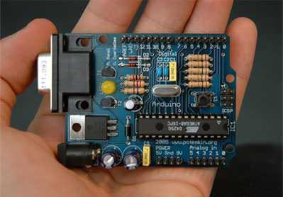
The first commercially available board was the Arduino RS232 featuring through-hole components, a DB-9 serial port, and a DC barrel jack power supply (Figure 3). This design made it easy to hand-solder and reproduce in decent quantities. The simple design, coupled with the decision to release the hardware design under a Creative Commons license (specifically a CC BY-SA license), propelled Arduino into the hearts and minds of countless artists and electronics hobbyists.
Figure 3: The Arduino Board Serial, one of the first commercially available boards. (Source: Arduino/Nicholas Zambetti)
Low cost was another consideration, as the Arduino was initially targeted at art and design college students. The decision to release the hardware and software (the IDE is released under a GNU general public license, version 2) is arguably one of the defining and, at the time, riskiest propositions for the then-fledgling electronics ecosystem. The pending closure of IDII in 2006 and its academic program being subsumed into the Domus Academy in Milan also helped prompt the founders to adopt an open-source model for Arduino.
In 2008, the five founding members of the Arduino project formed Arduino LLC to handle the intellectual property of the Arduino. It was initially envisioned that other companies would manufacture and sell the “official” Arduino boards while Arduino LLC would receive royalties from these sales. Of course, due to the open-source nature of the Arduino platform could take the design files and create both exact duplicates or improved boards (Figure 4). The only stipulation being they could not be named “Arduino” as that name was trademarked exclusively for boards licensed by Arduino LLC. Surprisingly while many derivative boards did find their way to the market, they did not have a significant negative impact on official board sales. Customers did indeed reward Arduino LLC with loyalty, recognizing the superior quality of the hardware and the effort Arduino LLC put into expanding the hardware platform and constantly improving the software development tools. Additionally, the form factor of the original Arduino boards has been faithfully maintained throughout the lineage of the credit card-sized Arduino boards, including the Diecimila, Duemilanove, and the current Uno R3.
Figure 4: The modern Arduino Integrated Development Environment (IDE). (Source: Green Shoe Garage)
It was not always smooth sailing for the Arduino LLC team. In the 2010s, a legal dispute erupted amongst the founders. Without rehashing this dark period, the bottom line was that the trademark Arduino was only good for boards sold in the United States. A company (Arduino SRL) run by one of the founders, Gianluca Martino, held the Arduino trademark in Italy. In response, Arduino began to market Arduino boards outside the United States as Genuino. For a few years, there was quite a bit of confusion in the Arduino ecosystem regarding which boards were compatible with which companies' development software. In 2017, the other four founders regained the trademarks held by Arduino SRL, and once again, Arduino was made whole.
Michael Parks, P.E. is the co-founder of Green Shoe Garage, a custom electronics design studio and embedded security research firm located in Western Maryland. He produces the Gears of Resistance Podcast to help raise public awareness of technical and scientific matters. Michael is also a licensed Professional Engineer in the state of Maryland and holds a Master’s degree in systems engineering from Johns Hopkins University.
Post Union Budget 2023-24, in an exclusive video interaction with K, Krishna Moorthy - CEO & President, and Anurag Awasthi - Vice President, Policy, Government Corporate Relations at India Electronics and Semiconductor Association (IESA) we came to know about how the global and the Indian ESDM and semiconductor industry is moving fo
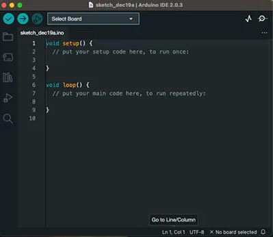
The Arduino platform is one of the most popular platforms for electronics enthusiasts and hobbyists for building electronic projects. Sometimes an Arduino board may not work as you might have expected and you might be wondering what the problem is. In this blog, we will learn the reasons why your Arduino board may not be working and how to solve it.
So, you’ve bought yourself a new Arduino. you plug your USB cable and it’s not powering up. No power led. No Rx or Tx led’s working. Let’s see what can be the issues:
If your Arduino is not showing any signs of powering up…you might check the following issues to sort your problem: -
Faulty Cable Issue:-
Inspect the cable for any signs of physical damage, such as frayed wires, kinks, or loose connections. If you see any type of damage, replace it.
Testing the cable: Use a multimeter to test the continuity of the cable. Test for continuity between each pin of the cable to ensure that it is properly connected.
Try a different cable: If you have another cable, try to use it to connect the Arduino to the power source or your computer. If the Arduino works with the new cable, then the old cable is likely the issue.
Check the USB port: If you are using a USB cable to connect the Arduino to the computer, try using a different USB port. Sometimes, a faulty USB port can cause connection issues.
Check the power supply: If you are using a power supply (I.e., power bank, adapter etc) to power the Arduino, make sure it is giving enough voltage and current. If the power supply is faulty, it can cause connection issues.If you have checked the cable and tried the above steps, but the Arduino still does not work, then it is possible that the issue is not related to the cable. In that case, you may need to troubleshoot.
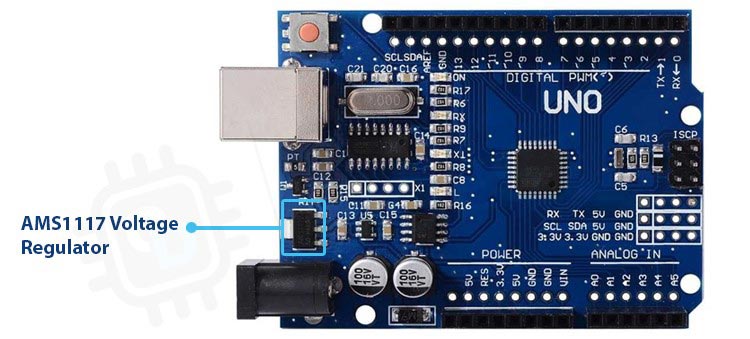
Voltage Regulator Faulty Issue:-
If you suspect that your AMS1117 voltage regulator is faulty in your Arduino project, here are some steps you can take to check and fix the issue:
Check the complete voltage regulator for any discrepancy visually.
Measure the input voltage of the ams1117 to ensure it is within the regulator's input voltage range provided in the datasheet. If the input voltage is higher than expected, consider adding a voltage divider or a Zener diode to reduce the input voltage to within the regulator's specified range.
Check the output voltage of the regulator and check that it is stable and within the expected range. If the output voltage is unstable or too low, test the capacitors on the input and output sides of the regulator. They should be within the recommended values and securely connected.
Check the regulator's current load capacity by measuring the current draw of the load and comparing it to the regulator's maximum output current rating in its datasheet. If the load current is more than the regulator's max output current rating, use a higher current rating regulator or add an extra regulator to share the load.
add a heat sink to the regulator to help dissipate heat and avoid a thermal shutdown.
Replace the faulty AMS1117 with a new one from a reliable supplier.
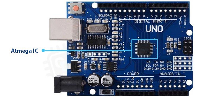
Atmega IC Faulty Issue:-
The majority of Arduino boards are controlled by the Atmega IC microcontroller chip. Here are some steps you can take to address the problem if you believe that the Atmega IC on your board is faulty:
Visual inspection: Look for any obvious symptoms of Atmega IC damage on the Arduino board, such as fractures, burns, or discoloration.
Verifying the connections: ensure that the Atmega IC is securely fastened to the circuit board and that none of the connectors or pins are flimsy.
Trying a different Atmega IC: If you have an additional Atmega IC or have access to one from another Arduino, consider swapping it out for the problematic one. If the Arduino functions properly with the new Atmega IC, the problem is with the older IC.
Testing with a programmer: If you have a programmer that is external, you can connect to it to test the functionality of the Atmega IC. Further setup will be necessary, such as the installation of the required drivers and software.
Changing the Atmega IC: If none of the aforementioned solutions resolve the problem, this step is required. To fix the broken IC on the Arduino board, get a replacement IC online or from a nearby electronics retailer.
Removing the Atmega Chip can be challenging and calls for some soldering expertise.
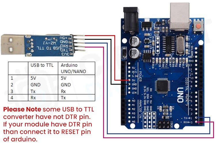
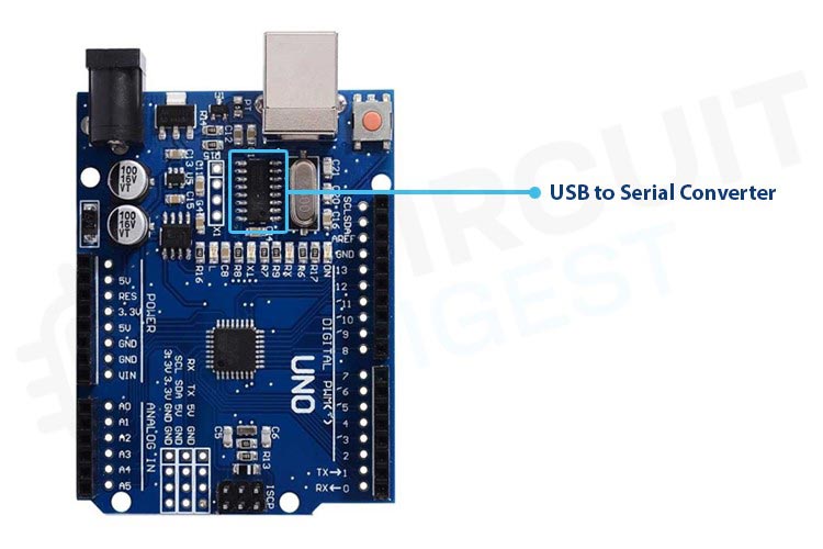
Serial Converter Faulty:-
If you believe that the serial converter on your Arduino board is broken (it's most likely a ch340 or cp2102). You can take the following actions to address the problem:
Look for connections: Check that the serial converter is securely attached to the board and that no connections or pins are loose.
Using a separate USB cord to check: Try a new USB cord if you are using one to connect the Arduino to the computer. An unreliable USB cord may occasionally result in connectivity problems.
Try connecting the Arduino to a separate system to test with a different computer (PC).
Examining the USB port: If you are connecting the Arduino to the computer with a USB cable, try a different USB port. An unreliable USB port may occasionally result in connectivity problems.
Verifying the power source: Verify that the power supply is supplying the Arduino with sufficient voltage and current. Connection problems may be brought on by a malfunctioning power supply.
Replace the serial converter: If none of the aforementioned measures work to solve the problem, a new serial converter may be required. A replacement serial converter is available from stores or online.
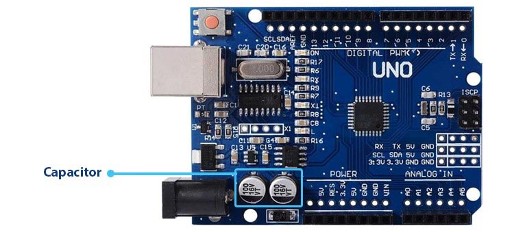
Main Capacitor Faulty:-
An Arduino board's primary capacitor aids in power supply stabilization and filtering. These are some steps you can take to solve the problem if you think the main capacitor is faulty:
Visual inspection: Check the capacitor visually for any obvious symptoms of damage, such as cracks, bulging, or leakage.
Test with a multimeter: A multimeter can be used to measure the capacitor's capacitance. The capacitance value must be same as the the value listed in the documentation for the Arduino board.
Checking the power supply: Check that the power source is supplying the Arduino board with the proper voltage and current. The primary capacitor may have some troubles as a result of a bad power supply.
Changing the capacitor: You must replace the capacitor if it is faulty. The defective capacitor on the Arduino board can be swapped out with a new one by placing an online purchase or visiting a nearby electronics retailer. Make sure the capacitor you choose has the same capacitance and voltage specifications as the original capacitor.
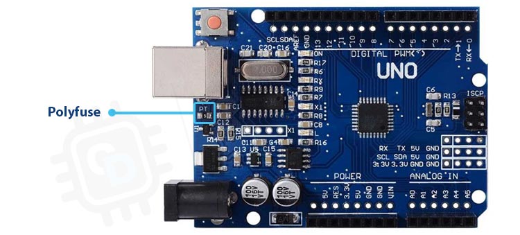
Polyfuse Faulty:-
Polyfuses are resetting fuses that shield an Arduino board's electronic parts from overcurrent and short circuits. Here are some steps you can take to troubleshoot the problem if you think your Arduino board's polyfuse is defective:
Visual inspection: Check the polyfuse for any cracks, bulges, or other outward indications of damage.
Test with a multimeter: A multimeter can be used to measure the polyfuse's resistance. While the polyfuse is in its normal state, the resistance should be low, and when it is blown, the resistance should be high.
Verify continuity: Examine continuity across the polyfuse using a multimeter. When the polyfuse is in its normal state, there should be continuity; when it is in its blown state, there should be none.
Check the power supply: Ensure that the power source is supplying the Arduino board with the proper voltage and current. The polyfuse may experience problems as a result of a bad power source.
Change the polyfuse: If the polyfuse is defective, you must change it. You can replace the defective polyfuse on the Arduino board by placing an online or offline order for a replacement polyfuse.
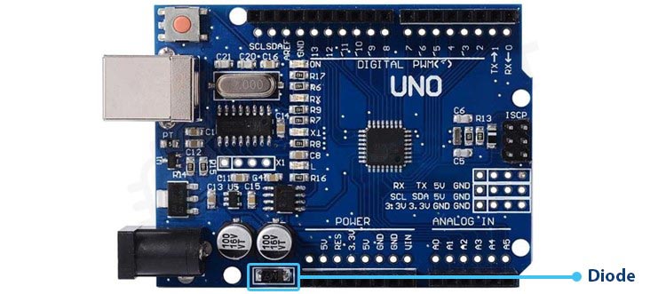
Diode Faulty:-
Diodes are used on an Arduino board to stop voltage spikes and restrict the direction in which current can go. If a diode on your Arduino board is broken, use these steps to fix the issue:
Visual inspection: Check the diode for any signs of damage, such as cracks or discoloration.
Do a multimeter test: Measure the voltage drop across the diode using a multimeter in both- forward and reverse orientations. The voltage loss should be within the ranges specified in the Arduino board's documentation. To get started with Multimeter, follow the link.
Do a continuity test by using a multimeter to look for continuity across the diode. The forward direction should go on forever, but the reverse direction shouldn't.
By examining the diode continuity, you may examine the power supply. Check to see that the power supply is providing the right voltage and current to the Arduino board. A bad power source could cause complications for the diode.
Replace the diode: If the diode is broken, you must do so. Get a replacement diode online or at a nearby electronics store to repair the broken one on the Arduino board.
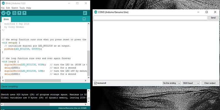
Board not in Sync
The "Board not in Sync" error message in Arduino IDE typically means that the computer is unable to establish communication with the Arduino board. This can happen due to various reasons, such as incorrect board selection, damaged USB cable, or wrong port selection.
Here are a few steps you can try to resolve the "Board not in Sync" error:
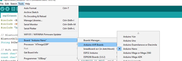
Ensure that the correct board is selected under the "Tools" menu. Check if the board type matches the one, you're using.
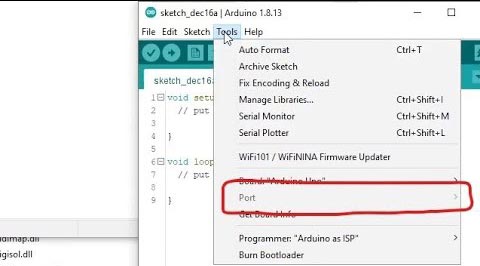
Check if the correct serial port is selected under the "Tools" menu. If you're unsure which port to select, disconnect the board, and see which port disappears from the list. Reconnect the board and select the corresponding port.
Try a different USB cable or USB port. A damaged USB cable or a faulty USB port can prevent communication between the computer and the board.
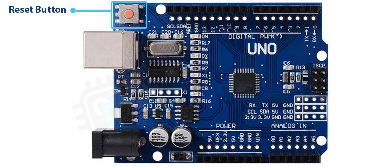
Press the reset button on the board while uploading the code. Some boards require you to press the reset button once the upload starts to get them into the bootloader mode.
Try uploading the code using another computer. If none of the above step’s work, try using a different computer to eliminate the possibility of a software or hardware issue with the original computer.
If none of the above step’s work, there may be a hardware issue with the board that needs further investigation.
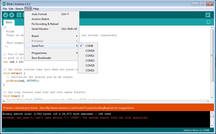
Wrong COM Port
This error in Arduino IDE means that the serial port which is selected is not the correct one for the Arduino board that you have connected. This happens when the board is not recognized by the computer or if multiple devices are connected to the computer, making it difficult to identify the correct port.
Here are a few steps you can try to resolve the "Wrong COM Port" error:
Disconnect the Arduino board from the computer and reconnect it.
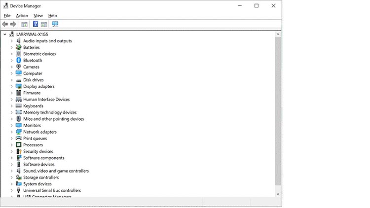
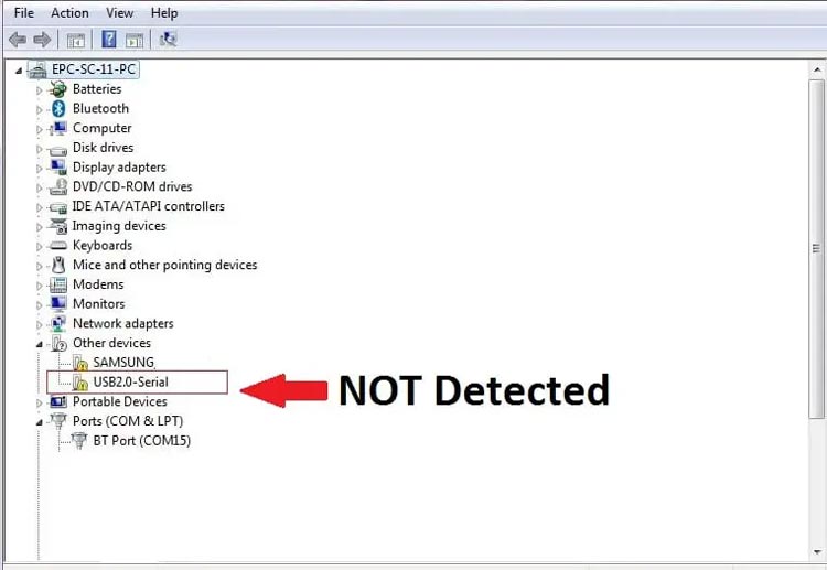
Check the Device Manager or System Information to see if the Arduino board is there under the Ports section. If it's not listed, the computer may not recognize the board, or there could be an issue with the USB cable or the board itself.
Check that the correct board is selected under the "Tools" menu. Check if the board type matches the one, you're using.
Check if the correct serial port is selected under the "Tools" menu. If you're unsure which port to select, disconnect the board, and see which port disappears from the list. Reconnect the board and select the corresponding port.
Try a different USB cable or USB port. A damaged USB cable or a faulty USB port can prevent communication between the computer and the board.
Restart the computer and the Arduino IDE. Sometimes, a simple restart can help resolve the issue.
If none of the above steps work, there may be a hardware issue with the board that needs further investigation.
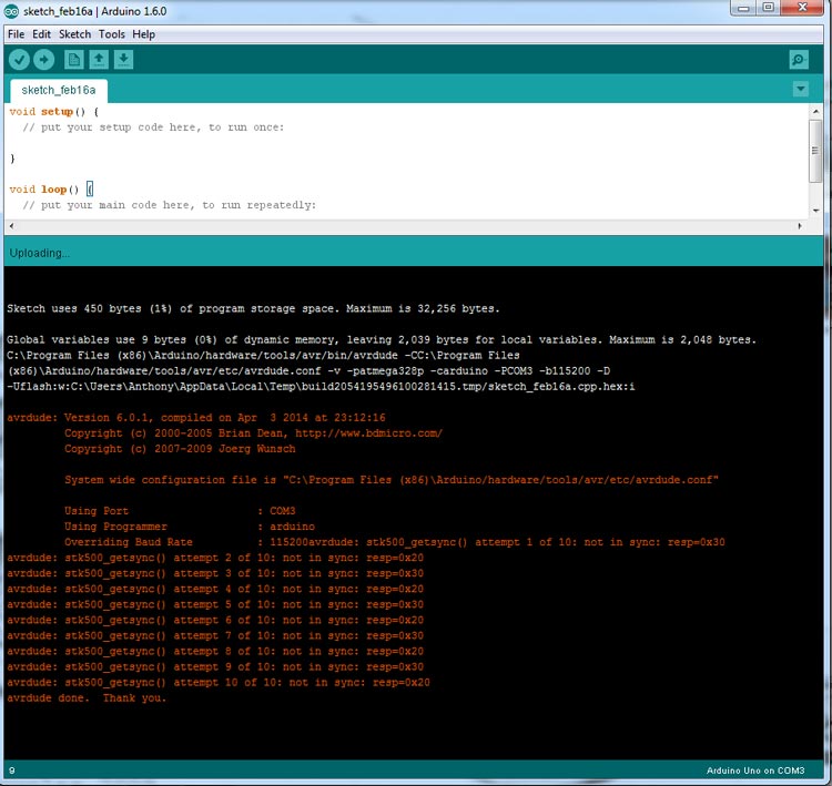
avrdude: stk500_getsync (): not in sync: resp=0x00
"avrdude: stk500 getsync (): not in sync: resp=0x00" often indicates that the computer is not able to connect to the Arduino board. This error can happen various reasons, including choosing wrong board, wrong port, having a corrupt bootloader, or a damaged USB cord.
To fix the "avrdude: stk500 getsync(): not in sync: resp=0x00" problem, try the following steps:
Check that your board is chosen in the "Tools" menu. Also check that the board type corresponds to the one you are using.
Verify that the proper serial port is chosen in the "Tools" menu. Disconnect the board and see which port vanishes from the list if you're confused which port to choose. Choose the appropriate port and reconnect the board.
Test a different USB port or cable. Communication between the computer and the board can be hampered by a broken USB cable or a defective USB port.
While uploading the code, press the reset button on the board. Some boards require you to click the reset button once the upload starts to bring them into the bootloader mode.
Try using a different computer to upload the code. If none of the above measures are successful, the board may have a hardware problem that requires additional research.
Arduino Board not Recognized
This indicates that the Arduino board is not recognised by the computer. A broken USB cable, improper driver installation, or a hardware problem with the board are just a few causes of this message.
You can try the following things to fix the "Arduino board not detected" error:
Verify that the USB cable is securely attached to the computer and the board. To test whether it fixes the problem, try some other USB cord.
Check that the board is turned on. Some boards need a battery or an external power source to operate effectively.
To see if the Arduino board is visible under the Ports section, check the Device Manager. If it isn't listed, there might be a problem with the USB cable or the board itself, or the computer might not be able to recognize the board.
Setting up the board's proper driver. A particular driver needs to be installed on the computer to support some boards. To get the correct driver and installation instructions, visit the manufacturer's website.
Restart the Arduino IDE and the computer. Sometimes all it takes to fix something is a restart.
Examine another USB port. The computer may be unable to recognize the board due to a broken USB port.
Try utilizing the board with a different computer. To rule out the potential that the original computer has a software or hardware problem, try utilizing the board on another computer if none of the previous methods work.
Bootloader Issue
Here are a few things you can do to solve the issue if you are having bootloader issues and none of the solutions mentioned above are working for your Arduino board:
Verify your USB cable: As you connect your computer to the Arduino board using a USB cable, check that everything is working properly. To test whether it fixes the problem, try a different USB cord.
Make sure you chose the right board and serial port in the Arduino IDE by checking your selections. Choose the proper board type and port from the "Tools" menu. Unplug the board, check the list of possible ports, plug the board back in, then check the list of ports once more if you are not sure which port to choose. The brand-new port that pops up must be the right one.
Clear the screen: By pushing the reset button, try to reset the board. The bootloader will restart as a result, enabling programming mode to be accessed by the board. After the board has been reset, make sure to immediately begin the upload procedure.
Burn the bootloader again: You might need to do this if the bootloader on your Arduino board is corrupted or not operating properly. On our website are instructions for burning the bootloader. It should be noted that an ISP programmer or another Arduino board acting as a programmer is required for this process.
Verify the fuse settings: Verify that the Arduino board's fuse settings are accurate. The board may not operate properly or the bootloader may not work at all if the fuse settings are off.
Serial Port Issues
Serial port issues in Arduino can occur due to various reasons, such as incorrect port selection, damaged USB cable, or a malfunctioning board.
Serial communication in Arduino refers to the process of sending and receiving data through the serial port of the Arduino board. Serial communication can be established between the Arduino board and another device such as a computer, another Arduino board, a sensor, or a display.
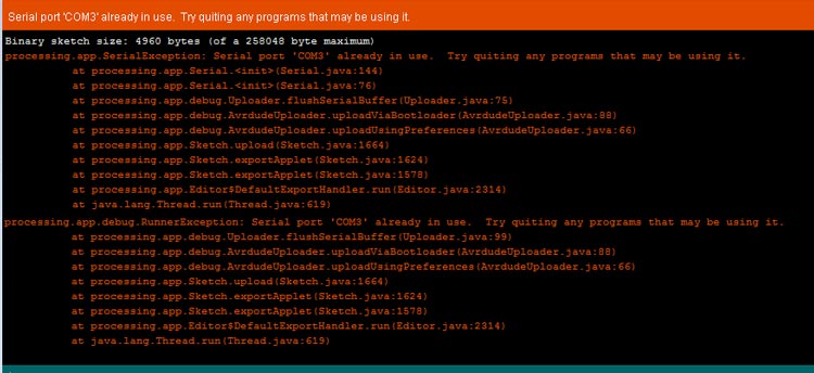
If you are getting a "Serial Port Already in Use" error message when trying to upload code to your Arduino board or trying to open the Serial Monitor, it means that the port you are trying to use is currently being used by another application or process on your computer. Here are some steps you can take to resolve this issue:
Close any other applications that may be using the serial port: Make sure that no other programs or applications are using the serial port that you want to use with your Arduino board. This could include other instances of the Arduino IDE, serial terminal software, or any other programs that use serial communications.
Disconnect and reconnect the Arduino board: Try disconnecting the USB cable from the Arduino board and then reconnecting it to see if that releases the serial port.
Restart your computer: Sometimes, the issue may be caused by a conflict with another software or process that is running on your computer. Try restarting your computer to see if that helps.
Use a different serial port: If your computer has multiple USB ports, try using a different port to see if that resolves the issue.
Check your code: Make sure that your code is not holding the serial port open or using it in a way that prevents other programs from accessing it.
If none of these step’s work, you may need to consult the Arduino forums or seek additional help from an expert.
Serial Port Menu Grayed Out: -
If the Serial Port menu is grayed out in the Arduino IDE, it usually means that the IDE is unable to detect any available serial ports on the computer. This can occur due to several reasons such as an incorrect board selected in the "Tools" menu, a damaged USB cable, or a malfunctioning board.
Here are a few steps you can try to resolve the issue:
Ensure that the board is connected to the computer via a USB cable and powered on.
Check if the correct board is selected in the "Tools" menu. If the board is not selected, the IDE may not be able to detect any available serial ports. Select the correct board from the "Tools" > "Board" menu.
Try using a different USB cable. Sometimes, a damaged USB cable can prevent the IDE from detecting the serial ports.
Try using the board on another computer. If the board works on another computer, it may indicate a hardware or driver issue with the original computer.
Reinstall the board's driver. Some boards require a specific driver to be installed on the computer. Check the manufacturer's website for the correct driver and installation instructions.
Restart the computer and the Arduino IDE. Sometimes, a simple restart can help resolve the issue.
If none of the above step’s work, there may be a hardware issue with the board that needs further investigation.
Serial Monitor Not Working:-
If you are experiencing issues with the Serial Monitor not working, there are several steps you can take to troubleshoot the problem:
Check your connections: Make sure your Arduino is properly connected to your computer and that the correct serial port is selected in the Arduino IDE.
Restart your Arduino IDE: Sometimes, the Serial Monitor can become unresponsive due to a software glitch. Closing and reopening the Arduino IDE can help to fix this issue.
Check your code: Make sure your code is properly written and that you have included the necessary Serial.begin() and Serial.print() statements.
Adjust the baud rate: Try adjusting the baud rate setting in the Serial Monitor. Sometimes, the default baud rate of 9600 may not work for certain projects.
Clear the buffer: If the Serial Monitor is displaying gibberish or incorrect data, try clearing the buffer by pressing the "Clear" button.
Reset your Arduino: Try resetting your Arduino by pressing the reset button on the board. This can sometimes help to fix issues with the Serial Monitor.
Try a different computer: If none of the above steps work, try connecting your Arduino to a different computer to see if the issue is with your hardware or software.
Sketch Too Large
If you are getting a "Sketch Too Large" error message when trying to upload code to your Arduino board, it means that the compiled code (or sketch) is too big to fit in the available program memory on the board. Here are some steps you can take to resolve this issue:
Optimize your code: One of the most effective ways to reduce the size of your code is to optimize it. This involves removing unnecessary code, using more efficient programming techniques, and minimizing the use of libraries or other resources that consume a lot of memory. There are many online resources available that provide tips and best practices for optimizing Arduino code.
Use a smaller board: If your code is too large to fit on your current board, you may need to consider using a smaller board with less program memory.
Remove unnecessary libraries: Libraries are a convenient way to add functionality to your Arduino project, but they can also consume a lot of program memory. Consider removing any libraries that you are not using or finding alternative libraries that are smaller or more efficient.
Use the F() macro for string literals: String literals (e.g. text messages) can consume a lot of program memory. To reduce their impact, you can use the F() macro to store them in flash memory instead of RAM.
Use PROGMEM to store data in flash memory: If your code includes large arrays or other data structures that are consuming a lot of program memory, you can use the PROGMEM directive to store them in flash memory instead of RAM.
Upgrade your hardware: If none of the above steps work and you absolutely need more program memory, you may need to consider upgrading to a board with more memory or using an external memory device.
By following these steps, you should be able to reduce the size of your code and resolve the "Sketch Too Large" error message.
Grounding Errors
Many things, including as improper wiring, shoddy connections, and electrical noise, might result in grounding issues in Arduino. These are some methods you can take to investigate and fix grounding issues:
Inspect your wiring: Verify that all of your connections and cables are secure and correctly linked. Errors in grounding can result from faulty or loose wiring.
Employ a dedicated ground wire: In some circumstances, connecting all of the circuit's components to a dedicated ground wire may be beneficial. This can lower the possibility of grounding problems and increase your system's overall reliability.
Isolate high-current and low-current wires: By doing this, you will lessen the chance that grounding errors will be caused by electrical noise and other types of interference.
Employ shielded wires: Shielded cables can reduce electrical interference and noise, which are frequent causes of grounding mistakes in Arduino circuits.
Utilize a power supply with a ground pin: Power supplies without a ground pin may result in incorrect grounding. To ensure appropriate grounding, utilise a power supply with a ground pin.
Employ decoupling capacitors to prevent electrical interference and noise, which are frequent causes of grounding problems in Arduino circuits. Decoupling capacitors should be placed as close as feasible to the component's ground and power pins.By following these steps, you should be able to troubleshoot and resolve grounding errors in your Arduino circuits
In this blog, we discussed some common issues that can occur when working with Arduino, along with steps to resolve them. By following the troubleshooting steps outlined in this blog, you should be able to resolve these issues and continue working with Arduino. However, it's important to remember that Arduino is a complex system and there may be other issues that can arise as well. If you continue to experience problems, don't hesitate to seek additional help from the Arduino community or an expert in the field. With patience and perseverance, you can become proficient in working with Arduino and enjoy the benefits of this powerful platform.
Looking to create your own audio spy bug? With an Arduino and the NRF24L01 module, you can create a compact and powerful bug that can transmit high-quality audio over long distances. In this blog, we'll guide you through the steps to create your own spy bug, from assembling the hardware to programming the software. With our step-by-step instructions and sample code, you'll be able to create a powerful spy bug that can pick up even the faintest sounds and transmit them wirelessly to your listening post. Don't miss out on this exciting project that will take your spy game to the next level!
Do you want to build your own digital multimeter? With an Arduino and some basic components, you can create a reliable and easy-to-use multimeter that can test voltage, resistance, LEDs, diodes, and continuity. In this blog, we'll guide you through the steps to build your own DIY digital multimeter, complete with a detailed parts list and step-by-step instructions. With our sample code, you'll be able to calibrate and test your multimeter to ensure accurate readings. Don't miss out on this fun and useful project that will help you become a better electronics hobbyist!
Do you want to build your own digital multimeter? With an Arduino and some basic components, you can create a reliable and easy-to-use multimeter that can test voltage, resistance, LEDs, diodes, and continuity. In this blog, we'll guide you through the steps to build your own DIY digital multimeter, complete with a detailed parts list and step-by-step instructions. With our sample code, you'll be able to calibrate and test your multimeter to ensure accurate readings. Don't miss out on this fun and useful project that will help you become a better electronics hobbyist!
The Taiwan based global semiconductor manufacturing firm TSMC, which is now equipped with the world’s largest foundry, is leading the industry. Chinese premier President Xi Jinping, who is considered to be one of the most powerful global leaders, has undertaken numerous efforts to reunify or invade the island country Taiwan. The danger of military takeover by China is increasing everyday. Now, on the other hand, the US is forming various strategies with its allies to defeat China in the global technology race and also to boost its growth in the chip industry. Since the time of the Trump administration Chinese giants like Huawei and ZTE were banned from providing services and solutions in the country. In fact Japan, which was once a preferred semiconductor destination is now trying hard to regain the growth like the 70s. Therefore, experts opine that Japan must increase their current strengths and must have amicable relationships with their equivalents overseas such as Taiwan and the US.
With the onset of COVID-19 pandemic in 2019, the global production of semiconductors slumped to a larger extent, which ultimately affected the international automobile and every chip-based sector. As per media reports, the worldwide sales of semiconductors towards the end of 2021 has reached $556 billion of which the US accounted for 46 percent. In fact, the global shares of top-notch semiconductor manufacturers in the US has degraded from 37 percent in 1990 to 12 percent until today. This is because the USA’s counterparts overseas have invested massively in semiconductor manufacturing coupled with billions of dollars of incentives. In an effort to revive its growth again, the US has finally unleashed the much-awaited CHIPS and Science Act in 2022 worth $52.7 billion.
What’s Leading the Semiconductor Geopolitical Scuffle
Semiconductors act as the brain of electronic devices and are playing an imperative role in shaping the digital economy. Now, the point is the upcoming cutting-edge semiconductors, which will be equipped with millions of transistors coupled with massive integrations are relying on the volume of investments. The chip manufacturing is now going through a lot of geopolitical scuffles, which is because of the fact that China now produces 25 percent of the semiconductors and is aiming to lead the global market. The remaining 75 percent of semiconductors are manufactured in East Asian countries such as Taiwan, South Korea, and Japan. Taiwan’s TSMC alone accounts for 90 percent of the advanced semiconductor manufacturing. Apart from Taiwan, one foundry is located in Nanjing, Shanghai, and in the US.
As per a previous report of the CircuitDigest, there were several heated discussions and speculations in the past couple of weeks regarding USA’s strenuous efforts to persuade Netherlands and Japan to join its league of no export of semiconductor technology to China. According to the experts, the US has been undertaking this strategy to boost its semiconductor industry and Japan and Netherlands will play an imperative role because they are the key providers of semiconductor manufacturing equipment. Although the US has the largest group of Integrated Device Manufacturers (IDM) for semiconductors, Netherland's ASML Technology and Japan's Advantest are the key players in this industry. ASML is the only company in the world that produces lithography machines that are utilized in making cutting-edge chipset. Therefore, if the country chooses to abide by Biden’s request, the matter will be a serious threat to China. Both India and the US have announced a strategic partnership on January 31 to boost the growth of semiconductors, space, defense, and modern technologies.
According to the experts, this association will help India to grab the benefits from initiatives on development, research, and the potential decrease of hurdles on US tech exports for supercomputers. Global experts have clearly added that by unleashing the CHIPS and the Science ACT, the US is looking to spearhead cutting-edge technology globally such as 6G, quantum computing, and artificial intelligence. Before the alliance with India, the US decided to craft a ‘Chip 4’ association with Taiwan, South Korea, and Japan to build a strong semiconductor supply chain that will keep out China.
Against the USA’s critical strategy of curbing export of key semiconductor technology to China, the latter has carried out a dispute against the former at the World Trade Organization (WTO) a month back. This is because of the fact that the world’s second largest economy with a GDP of 23.32 trillion dollars feels that they could be under a serious financial tussle. Back in October 2022, the USA had formed rules that stopped export of chips to China made from American technology and also American citizens working in Chinese firms are fearing of losing their jobs or risking their US citizenship. This move has severely affected China’s semiconductor industry and other high-tech industries. Because of these stern situations, the Chinese Ministry of Commerce confirmed the trade dispute in a media briefing and harshly criticized the US for misusing export control rules and fetching obstacles in global trade in chips and other tech products.
The WTO argued that tariffs foisted by President Trump on imported aluminum and steel deeply contravened international trade policy and this is when China initiated the tech trade dispute against the US, as per a report of CNBC. Experts opined that trade disputes in the WTO can take numerous years for a possible solution. The point to be noted is that WTO also has rules that says every country has the right to impose curtailment of export in the interest of national security. Hence, it could be difficult for China to win this battle.
In an interaction with CircuitDigest, Samrendra Mohan Kumar, Founder & MD, MitKat Advisory said, “In the coming years, the communist government in China will play a significant role in increasing the financial strength of the country and it could be harsh. Li Qiang who is now spearheading the economic policy of China has framed various policies, which are yet to be implemented. Currently, the country still depends on the US and other countries for key technology and intellectual property for its semiconductor manufacturing. After COVID, global firms have decided to move out of China and semiconductor firms such as TSMC, Intel, Samsung, and many more are investing massively in the American market and also in India. Attractive measures are also launched by the EU to magnetize chief semiconductor firms.”
How The Global Semiconductor Battle Can Benefit India?
If we go by history, Bengaluru has turned out to be a hotspot for IT and technology in 1985 and it also gave birth to the semiconductor industry. The commencement of the semiconductor journey seemed to be very propitious, but unfortunately the revolution lost balance. It then helped South Korea, Taiwan, Japan, and China to lead the race. As per a report of The Print, semiconductor Complex Ltd (SCL), which was a government owned fabrication foundry in Punjab caught fire in 1989 and the numerous government initiatives were blown over. Rather than focusing on manufacturing, the country focussed deeply on chip design between the 1990s to 2000s. The nation now imports 100 percent of chips and it was negatively impacted by the global shortage of semiconductors due to Covid and the Russian-Ukraine tussle.
To achieve self-sufficiency and stop relying on imports, the government unleashed the much-anticipated PLI scheme of Rs 76,000 crore to boost display and semiconductor manufacturing. Also, a panel has been formed in April 2022 to assist start-ups and MSMEs in this industry. Now, there are various globals investments in the country in semiconductor manufacturing like investment from Singapore’s IGSS Ventures, Vedanta-Foxconn deal, Tata Group’s foray into manufacturing of chips, and Next Orbit Ventures and Israel’s Tower Semiconductor announcement of a $3 billion chip plant in Karnataka.
Now, the point is how China Plus One Strategy and USA’s export ban strategy will help India to grow its ESDM sector. The US is trying hard to pull out the supply chain strengths from China by forming amicable relationships with its allies such as the Netherlands, Japan, Taiwan, and India. The White House has assured India to build its semiconductor industry due to which the latter is expecting to unleash an investment of $25 billion as an incentive scheme. The aim is to make India a key competitor in the international supply chain. In a recent interaction with The Diplomat, Sunil G. Acharya, vice president at India Electronics & Semiconductor Association (IESA) mentioned that the semiconductor major firms such as Micron, Intel, and Texas Instruments are all operating in India who are providing support services and designs. Apart from that, there are a couple of well-known fabless domestic firms who provide design services to numerous international companies. Acharya further added that due to the unleashing of the SCIENCE and Chips Act, the US based chip firms will be able to expand their support services, R&D, and design centers in India.
Faisal Kawoosa, Senior Research Analyst and founder at techARC told CircuitDigest, “ChinaPlus One Strategy is already helping India to grow its ESDM sector in various ways and the alliance with the USA will give India further impetus to boost its semiconductor industry both in terms of investment and revenues. The major problem is China is still leading the component industry and without that you can grow your industry. Therefore, both India and the US must find solutions to grow its component sector. Even if you set-up manufacturing bases you are still importing a huge chunk of components from China. Global investments have already happened in India and I am sure the close association with the US will make India a major player in the ESDM sector internationally.”
Geopolitics surely has a say as every major country has now put semiconductors as an important pill and there is an urgency as every key semi-country also depends on imports of various kinds of chips as well. It's the IP that is at stake here and the race is on....US, Korea specialize in high value advance chips and China needs to play a catch game here. All this means that diversification will happen, claim experts.
Tarun Pathak, Research Director, Devices and Ecosystems at Counterpoint Research told CircuitDigest, "As no one would like to put eggs in one basket. India has an added advantage in terms of design experts as leading semiconductor companies have design houses here and It's the manufacturing and IP where we catch up and we believe India is at the right place at the right time. Semi content within categories is increasing, while the electronic devices growth will continue too. Promoting product design, including both hardware and software can be a first step in making India a hub for the electronics system design and manufacturing sector. India semiconductor market consumption is all set to reach $64Bn by 2026 with a CAGR of 16 percent."
Of late, various reforms and policy measures have been announced with an aim of escalating the share of manufacturing in gross value added (GVA) to 25 percent. In the financial year of 2019-20, the manufacturing cluster offered 17.1 percent of GVA and exports accounted for 20.7 percent of the overall manufacturing yield. The point to be noted is that none of the computer chips are completely manufactured in India yet and although US semiconductor firms have shown a lot of optimism to India there is still a discrepancy between what has been committed in eloquence and what has been assured in a signed document.


 Michael Parks, P.E. is the co-founder of Green Shoe Garage, a custom electronics design studio and embedded security research firm located in Western Maryland. He produces the Gears of Resistance Podcast to help raise public awareness of technical and scientific matters. Michael is also a licensed Professional Engineer in the state of Maryland and holds a Master’s degree in systems engineering from Johns Hopkins University.