What is Helping the Growth of the Global Cellular IoT Module Market?

Smart meters along with automotive, router/CPE, industrial, PC and POS are the major IoT based cellular applications that helped in generating large revenue, but router/CPE, PC, and drones are the key three growing segments

For the international deployments of IoT, cellular connectivity is known to be the impeccable and trustworthy connection option. There are no requirements to craft new-fangled infrastructure nor adding of further network gateways to support deployments remotely. It implies that cell towers are simply getting connected that already existed. Another thing that can be looked upon is cellular roaming. As the cellular IoT ventures move from location to location there must be an agreement or an association between partner carriers and your cellular providers to allow seamless connectivity throughout the regions devoid of changing the SIMs. Now, the point to be noted is that as the cellular network utilizes SIM cards for authentication, it becomes very intricate to find the identity of the product. In the IoT ecosystem, if any sole device is under security risk then all the products related to it are at risk severely. In order to assure the security of the device is safe, the cellular keeps on separating every device from every other device.

Now, the reliability of the cellular device is another criterion. As cellular connections gained massive traction and popularity all over the world, the Cellular IoT protocols can grab the advantages or the benefits of the existing characteristics and benefits. In the licensed bands, the cellular works that state the reliability and performance of the communication. However, cellular also offers a huge volume of connections per tower, which are monitored and supervised separately thus offering success and guarantees on reliability and services. If you look back closely at history, a significant limitation for cellular adoption has been battery life and power usage. The cellular protocols of this generation would make it easier for cellular IoT modules to cut power costs when they are not being used and transmit a small volume of data with the slightest power usage. In this regard, both NB-IoT and LTE-M have been designed exclusively to provide top-notch operation from a power source driven by a battery. As the data throughput is not largely available, lesser intricate radio modems and easy signal modulation schemes are massively required, leading to lesser power requirements. On modern hardware, improvements in sleep/wake modes provide the benefits mentioned above.

New Role of Technology in Cellular IoT Module Market

Now, according to various telecommunication experts, the connectivity landscape in China is completely different from other parts of the planet. Now, if you look at the countries outside China, the piercing of LTE-Cat 1 is much higher, for instance, the perforation of narrowband (NB)-IoT. In China, only 12 percent of penetration is done by LTE-Cat 1, while the same offers 23 percent penetration outside China. According to an exclusive report of IoT Analytics, back in 2020, the Cellular/licensed low-power wide-area (LPWA) shipments (NB-IoT and long-term evolution-machine type communication LTE-M) offered only 10 percent of the market outside China. The country is mostly focused on improving NB-IoT and 90 percent of this shipment appeared from China itself.

Highlighting the importance of cellular IoT modules, Satyajit Sinha, Senior Analyst, IoT Analytics said in his research report, "The rise of LTE-Cat 1 started in North America a few years ago. That is when LTE-Cat 1 started to become the go-to alternative for 2G and 3G IoT applications as 2G networks were retired by network operators. The massive migration from 2G/3G to LTE-Cat 1 started in 2018. Telit, Thales, and Sierra Wireless, for example, have collectively shipped more than 40 million LTE-Cat 1 modules in the last three years in the outside-China region. As evidenced in the data, the decline in shipments of 2G/3G modules was directly proportional to the increase in shipments of LTE-Cat 1 modules outside of China."

In the past few years in China, for 2G IoT applications, NB-IoT has turned out to be the new substitute. Therefore, in China, NB-IoT has turned out to be the licensed low-power wide-area network (LPWA) technology of choice. Nonetheless, the technology LTE-M is not present in China and certain technical hindrances within NB-IoT have spearheaded the escalating demand for a new-fangled segment, which is low-cost LTE-Cat 1 bis modules that are centered on 3rd Generation Partnership Project’s (3GPP) Release 13. The technology is optimized for lesser power applications and a sole antenna. "This is in contrast to the LTE-Cat 1 standard adopted in North America, which is defined by 3GPP’s Release 8 and is supported by two receive (Rx) antennas. 3GPP’s Release 8 LTE-Cat 1 is based on Intel and Qualcomm chipsets, whereas 3GPP’s Release 13 LTE-Cat 1 bis is driven by UNISOC 8910DM. The Release 8 LTE-Cat 1 modules cost, on average, $10 more than the Release 13 LTE-Cat 1 modules," added Sinha in his research.

Cellular IoT Module Market

Growth of Global Cellular IoT Module

A new research report of Counterpoint stated that in the final quarter of 2020, the growth in revenue of international cellular IoT modules escalated to 58 percent YoY. China is claimed to be the fastest adopting this technology and managed to grab more than 40 percent of the profit. India is said to be the fastest-growing cellular IoT module market with a market share of 324 percent YoY, which is then followed by 4G Cat 1 105 percent. Router/CPE, PC, and industrial were the leading applications for 5G. Highlighting the importance, Senior Analyst of Counterpoint Soumen Mandal opined that MeiG, Quectel, and Telit managed to grab the top three stands in the worldwide cellular IoT module market. In Q4 2021, these firms offered around 40 percent of the revenue, whereas the revenues and the shipments of this technology reached 57 percent and 59 percent YoY.

MeiG is one of the leading Chinese firms in this domain that is looking for constant enhancement and development and has now finally reached the top three standings on the cellular IoT module cluster both in terms of revenue and shipment. The company is carrying out more development and research on AIoT and smart module-based higher-end applications such as router/CPE, intelligent cockpit, video recordings, industrial PDAs, drones, and AR/VR. Now, in 2021, the company entered into the business of lower-end applications. This product amalgamation of low-priced and flagship modules assisted the company to augment revenue by more than 100 percent in Q4 2021.

Quectel's recently launched ODM brand, Ikotek, which will throw tough competition in the US. Again in Q4, 2021, the revenue in the same segment escalated to 100 percent YoY. Experts are now speculating that this firm would make its entry into the Latin and North American markets. According to the said requirement of a venture, the products can be customized and designed accordingly. On the other hand, Telit made a strong comeback after relatively weaker performance in recent history. For quite a few years, Telit is constantly increasing its solutions and services, which is helping its growth, whereas, Telit NExT is offering seamless connectivity schemes throughout the 190 countries to grab the benefits of growing business models and wiping out key bottlenecks for several IoT vendors, mostly device based. In Q42021, the company largely focussed on Latin America to assist customers from migrating to 4G cat modules. The strategy helped the company to become the major supplier of modules in the country and it ultimately maintained its key position in the North American market.

Global Cellular IoT Module Vendor Shipment Ranking

According to a report by Counterpoint Research, the other important firms in this segment are Sierra Wireless, Rolling Wireless, Fibocom, Thales, and Sunsea and among all the companies, LG and Rolling Wireless mostly catering to the automotive segment. Thales is centered on industrial applications, smart meters, and healthcare mostly in Japan, North America, and Europe. Fibocom is said to be working exceptionally well in 4G Cat 1 bis technology, but the company failed to include itself in the top five standings in module vendors due to its inferior performance of the NB-IoT module. Sunsea on the other worked quite well in the worldwide IoT module market, but still, its shares went down. Sierra Wireless’s and Rolling Wireless’s profits soared to 87 percent and 105 percent respectively. After rolling out from Sierra’s automotive segment last year, Rolling Wireless swiftly included itself in the top ten module vendors list.

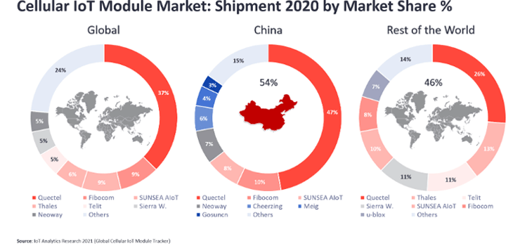
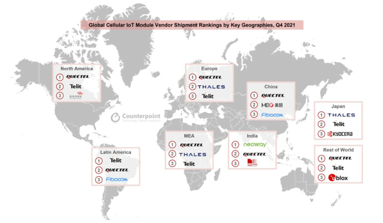
Senior Research Associate Neil Shah said, “Back in Q4 2020, the global module vendors did not perform well, but in the same quarter of 2021, the same companies performed exceptionally well. In terms of profit in China, Sunsea, Quectel, and MeiG turned out to be the top IoT module firms. But, other than China, Thales, Quectel, and Telit were the top three players in the market. Quectel is ruling the sector in Japan, Latin America, and India. But, these same regions have a very diminutive share of cellular IoT modules, and hence, they do not have much impact. Japan has a preference for LTE-M, which is against the business model of Quectel.

Have any question realated to this Article?

Ask Our Community Members

Build a 300W Pure Sine Wave Inverter

Nowadays we can’t even imagine a world without power. Even an intermittent power failure is so inconvenient. As we depend on electricity in many important areas of our life, it is important to take persuasion against power failures and that’s where the inverter plays an important role. There are multiple types of inverters in the market, such as square wave inverters, modified sine wave inverters, and pure sine wave inverters. The cheapest options would be square wave and modified sine wave inverters. But the difference between modified and pure sine wave inverters is that these types of inverters are not suitable for inductive loads such as motors, fans, etc. that’s where pure sine wave inverters come into play. They output a pure sinewave at line frequency so that it won’t affect such inductive loads.

So, in this project, we are going to build a pure sine wave inverter with a rating of 300W or 800VA. Let’s look at the components needed for this project.

Components Required

  • EGS002 SPWM module
  • IRF3205 N Channel MOSFETs
  • 90N03 N Channel MOSFET
  • LM7505 Voltage regulator
  • FR207 Diodes
  • S8050 Transistor
  • 12V fan
  • 10 Ohms resistors
  • 1 KOhms resistor
  • 1 KOhms resistor
  • 10 KOhms NTC
  • 10 KOhms Preset
  • 0.1uF capacitors
  • 2.2uF 650V Capacitor
  • 10uF capacitors
  • 2200uF capacitor
  • 0-9V Transformer with a rating of 400W or higher
  • Heat Sink
  • Connectors
  • Wires
  • Copper Clad / Perfboard
  • Soldering Kit

300W Pure Sine Wave Inverter Circuit Diagram

The complete circuit diagram for the Pure Sine Wave inverter is given below.

300W Pure Sine Wave Inverter Circuit Diagram

Now let’s have a look at each section.

The power section consists of reverse polarity protection based on an N Channel MOSFET and an LM7805 voltage regulator along with some filter capacitors. The input from the battery is connected to the power input and then the positive is directly connected to a switch and the H-bridge. The negative is connected through an N Channel MOSFET for reverse polarity protection. LM7805 generates the necessary 5V for the EGS002 Module.

Pure Sine Wave Inverter Power Section

The temperature and fan control circuitry consists of a 10K NTC for temperature measurement and an NPN transistor to drive the fan. The temperature reading and the fan control are done by the EGS002 module itself.

Temperature and Fan Control Circuitry

Next, the H-Bridge and EGS002 control circuit. The H-Bridge is made up of four IRF3205 MOSFETs. The control lines from the EGS002 are connected to the MOSFETs through the gate resistors. The transformer is connected to the points TR1 and TR2.

H-Bridge and EGS002 Control Circuit

The feedback circuit consists of a bridge rectifier and a voltage divider. The variable resistor VR1 is used to adjust the output voltage by adjusting the feedback voltage. The AC voltage from the transformer is connected to the input of the bridge rectifier and the step-down voltage is connected to the VFB pin of the EGS002 module. The module will adjust the SPWM duty cycle with respect to this feedback voltage, to keep the output voltage stable.

Sinewave Inverter Feedback Circuit

The transformer is connected to the H-Bridge at TR1 and TR2 points. In the output, a 2.2uF 650V capacitor is connected to filter out any high-frequency component from the SPWM. This filtered output is then connected to load and a feedback line of the EGS002.

Sinewave Inverter Transformer Circuit

Building and Testing the Pure Sine Wave Inverter Circuit

You can either build this project in a perfboard or you can make a PCB with the files from the link at the bottom of the page. Both PDF files for the toner transfer method and the Gerber file for the manufacturing are included. Here is the PCB layout for the inverter.

EGS002 Driver Board

And here is the PCV view for the same.

EGS002 Driver Module

Once you made the circuit with all appropriate connections, connect the battery and turn on the switch. If the inverter turns off after a few seconds with the LED on the EGS002 blinking three times, it is because the output voltage is not calibrated. Connect the output to a TrueRMS multimeter and adjust the variable resistor till the output voltage is set correctly.

Pure Sine Wave Inverter

Once the voltage is set the inverter will work without any errors. The EGS002 Module has a Low Voltage cut-off, so if the input voltage is reduced below minimum voltage the inverter will shut down automatically. Similarly, the module is featured with overcurrent protection and over-temperature protection. Let’s have a look at the EGS002 Module and its features.

PCB And Main Components

Here is the PCB I have made, and the components used. You can see that the number of components is the bare minimum. The input is given through a high gauge wirer to reduce the voltage drop due to the resistance of the conductor. A tank capacitor of 2200uf is added to the input. The 5V for the EGS002 module is generated using the LM7805 voltage regulator and the filter capacitors. As already mentioned, the AC feedback circuit consists of a bridge diode made of four FR207 diodes, a voltage divider made of two 100KOhms resistors and a 10KOhms pre-set and a filter capacitor of value 10uF.

Pure Sine Wave Inverter Module

Here is the H-bridge circuit made of four N channel MOSFETs. You can use IRF3025 or any compatible ones for the H-Bridge circuit.

H-Bridge Circuit Setup

The below image shows the bottom side of the PCB. The bottom side only has one component. And that is an N-Channel MOSFET for the reverse polarity protection. The power traces are reinforced with solder for better current handling. All other traces are covered with solder to avoid the oxidisation on the home made PCB tracks.

EGS002 Module

EGS002 Module

EGS002 is a driver board, designed for single-phase sinusoid inverters. It uses ASIC EG8010 as the control chip and IR2110S as the MOSFET driver chip. The driver board integrates functions of voltage, current and temperature protection, LED warning indication, and fan control. We can use jumpers to configure the following settings, Output frequency (50/60Hz), soft start mode, and dead time.

Here is the pin description table for the EGS002 module-

EGS002 Module Pin Description

Jumper Configurations

As already mentioned, the EGS002 can be configured with the onboard jumpers. Let’s take a look at those. The following table shows the function of each of these jumpers.

EGS002 Module Jumper Configuration

LED Indications and Error Codes:

The EGS002 module can give error codes with the onboard LED. Here are the error codes and their meanings.

Normal: Lighting always on

Overcurrent: Blink twice, off for 2 seconds, and keep cycling

Overvoltage: Blink 3 times, off for 2 seconds, and keep cycling

Undervoltage: Blink 4 times, off for 2 seconds, and keep cycling

Overtemperature: Blink 5 times, off for 2 seconds, and keep cycling

Working of the 300W Pure Sinewave Inverter

The below gif shows the working of the pure sine wave inverter. The GIF showcases the soft start of the inverter.

Here is the waveform view of the inverter output.

Pure Sinewave Inverter Output Waveform

You can increase the inverter power by adding more MOSFETs and changing the transformer. All the files necessary to build this project can be found in the following GitHub repo.

Have any question realated to this Article?

Ask Our Community Members

There is a 90% Decline in Solar Cost Trend in India in the Last Ten Years

Of late, Mordor Intelligence, a market research firm stated that the market for solar energy in India is speculated to reach a CAGR of 8 percent from 2020 until the end of 2027. In fact, experts also highlighted that the COVID-19 pandemic failed to impact the market in India because a sufficient volume of growth was already viewed in the solar PV installed capacity in 2020 compared to 2019.

Teardown of 3S, 6A Lithium Ion Battery Management and Protection Module (BMS) with Schematics, Parts List and Working

In this article, we will be learning about the features and working of a 3S 6A lithium Battery Management System or BMS along with checking out the components and the circuitry of this module. Furthermore, we have done complete reverse engineering of the module by removing all the components from the PCB and measuring all the PCB traces with the multimeter. For testing the BMS and the circuit, we have built a battery pack and we will charge and discharge the battery pack with it. 

Protection Features Offered by JW3313S based 3S 6A BMS Module

A BMS is an essential component for any battery pack not only because it protects the battery from overcharge and over-discharge conditions but it also extends the service life of a battery by keeping the battery pack safe from any potential hazard. For this, we are using a 3S, 6A battery pack which houses a JW3313S Battery Protection IC. The protection features available in the Battery Management System are listed below.

  • Overcharge detection
  • Over Discharge detection
  • short circuit detection voltage

Overcharge Condition:

When a lithium battery is charged beyond a safe charging voltage, the cell heats up extremely and its health is affected and its life cycle and current carrying capacity get reduced. To protect the cell from these types of conditions, a good battery management system must have an overvoltage built-in, and for the JW3313S IC, this is no exception. In our testing charging of the battery pack cut off almost at 12.75V which represents 4.25V for each cell.

Over Discharge Condition:

The same can be said true for the over-discharge protection. When the battery voltage goes below a certain threshold, the lithium cells get affected and the life cycle of the cells gets reduced. To protect this from happening, every BMS should have over-discharge protection and this IC is not an exception. In our testing, the cell voltage gets as low as 2.7V for each cell, and then the protection features kicked in and cut the output.

Short Circuit Condition:

Overcurrent protection in a BMS is necessary to safeguard the battery from high current load or short circuit conditions. When a short circuit condition occurs the current draw is way higher than the maximum rated current of the battery pack. This condition can affect the cell’s health or even cause damage to the cell leading to fires. This is also why there is an overcurrent and short circuit protection built into the chip.

Note: Please note that along with all the protection features, the JW3313S features hysteresis. When the overcharge protection kicks in, the battery gets disconnected and stops charging the battery. This causes the battery voltage to go slightly lower than the cutoff voltage. Now the battery will start charging again and the process will continue infinitely. Adding some hysteresis will prevent this.

Components used in 3S 6A BMS Module

Before we take a look at the schematic, here is the list of components that are required to build the 3S 6A BMS module. The main controlling IC of the board is the JW3313S Protection IC which is an 8-pin IC designed and developed by a Chinese manufacturer joulwatt. On the board, we have two FL3095K MOSFETs and a 0.005R Resistor. Other than that, we have a few resistors and capacitors as you can see in the image below. The list of components needed to build this module is shown below.

3S,6A Lithium Ion BMS Module Components

  • JW3313S low-power battery protection IC -2
  • FL3095K Mosfets - 2
  • 1N4148 - 1
  • 0.1uF Capacitors  - 5
  • 0.15uF Capacitors  - 1
  • 1K Resistor - 4
  • 10K Resistor - 3
  • 2M Resistor - 1
  • 1uF Capacitor - 1

Circuit Diagram of the 3S 6A BMS Module

The schematic of this BMS is designed using Eagle PCB Design Software. As you can see from the image below, it's not that hard to understand the complete circuit diagram of the 3S 6A BMS circuit.

3S 6A Lithium Ion Battery Management and Protection Module (BMS) Schematic

As you can see, we have the JW3313S chip that controls all the operations of the device. If you carefully observe the module, you will see separate connection terminals for P+ and B+. On the board, P+ stands for positive power input and output and B+ stands for Battery Pack Positive Input. In the PCB, these two terminals are connected to each other so we have named the connection P+B+. Next, we have the CO and the DO pins of the IC, which are pin 8 and 7 of the IC., which controls two MOSFETs. The CO gets high when an overcharger condition occurs. The DO gets high when an over discharge condition occurs. Next is pin 6 of the IC which is marked VM in the schematic and with this pin, the IC sets the over current protection of the device. This IC was designed so that it could use the internal resistance of the MOSFETs to detect the current but in this case, as you can see the manufacturers used a separate current shunt because they are using a Mosfet with high internal resistance. Pin 1 of the device is the power pin that supplies power to the IC and pins 2,3, and 4 are individual sense pins of the BMS module, and pin 5 is the ground pin of the module. Other than that, there are a couple of resistors and capacitors which are used for filtration and current limiting.

BMS Connection with Battery Pack - Fritzing Schematic

The BMS module has 4 terminals that will get connected to the four different points of the battery pack. This way the BMS module can separately monitor three individual cells and protect them from overcharging or over discharging. The schematic diagram of the BMS is shown below.

BMS Module with Battery Pack Connection

The BMS acts like three individual protection modules for three individual cells but it's a single IC that integrates all the features together to make the BMS that is able to deliver recurrent up to 6Amps.

Testing the 3S6A BMS Module for Overvoltage, Undervoltage & Short Circuit

Let's test the BMS and see if the BMS module is working as advertised in the datasheet. We are using a 3S 6A BMS module that uses a JW3313S Battery Protection IC and this IC is designed and developed by Joultech which is a Chinese manufacturer. You can check out Joulwatt website for more information on the IC.

Overvoltage Protection Test:

We started our test by arranging the battery packs in 3S configurations and started the charging process with a constant current of 600mA.

According to the datasheet, the charging process should have stopped when the pack voltage reached 13.125V that is 4.375V/Cell but to our surprise the battery got overcharged and started heating up then we stopped the charging. We don't know if this was the problem with our particular BMS board or not. We repeated our test with a new module but the result was exactly the same. You can see the testing process in the gif above.

Undervoltage Protection Test:

when the battery pack was fully charged (In our case it was overcharged), we started our undervoltage protection test.

As you can see in the above image for the under-voltage test we have removed one battery from the battery holder and replaced it with our Regulated Power Supply(RPS). Now we are decreasing the voltage and as you can see from the above gif, the BMS cuts out the load below 2.8V which means there are two protection systems that are working simultaneously. First, the BMS is monitoring the pack voltage and second, the BMS is monitoring individual cell voltage. If any one cell gets damaged the BMS will cut power.

Short Circuit Protection Test:

When the over voltage and under voltage protection test was done we need to check if the BMS was able to protect the battery pack from short circuit and overload conditions.

For that, we have connected a multimeter with the output of the BMS module, and as you can see when we short circuit the output of the module with the multimeter probe, the voltage goes to zero and you cannot see anything that is catching fire. This indicates that the short circuit safety mechanism is functioning properly.

Conclusion

The 3S 6A BMS module is a cost-efficient and highly effective module to protect LI-PO or LI-ION cells from damage. The 6A power capacity makes this device very versatile because not only this device can be used for three series packs, but it can also be used to make three series and two parallel battery packs that can be useful for many projects.

Have any question realated to this Article?

Ask Our Community Members

Semiconductor Industry is Expected to Reach the Trillion-dollar Mark by the End of this Decade

For the past few years, India’s semiconductor industry has been transforming at a massive scale with the help of various schemes and initiatives unleashed by the government. But, when we speak of infrastructure, the nation has only one foundry and OSAT. There are infrastructure challenges (continuous power, water) in maintaining such manufacturing units. The PLI scheme can help build more foundries and OSATs in India to support end-to-end solutions development.

The Semiconductor Industry will Have a Strong Growth in 2022 in all End Markets and Regions

Back in 2021, when the semiconductor shortages forced car-makers to halt a huge line of production, the semiconductor industry witnessed its importance and found the spotlight. Everywhere people were discussing the tiny product that helps in various car functions from interior lighting to seat control to blind-spot detection. Now, when the IT hardware and consumer electronic firms started witnessing chip shortages from 2020 and supply chain imbalance, the attention increased. Scores of challenges then surrounded the semiconductor industry and the shortage.

What are the Requirements to Expand, Enhance Semiconductor Supply Chains?

As the Russian-Ukrainian fracas continues, various countries and firms are now busy in evaluating where the upcoming disturbance and disruption in the supply chain will happen. Now, as the financial frictions escalate between China and other western countries, a huge concern over China’s dominating action on Taiwan has augmented. These worries have spotted the requirements of  superior visibility of sub-tier supply chains for intricate items like semiconductors, and also the necessity of cleverly expanding the global semiconductor supply chains. Interestingly, in Taiwan, TSMC solely grabbed the vast majority of market share of 53.1 percent, which is then followed by Samsung Electronics 17.1 percent, and UMC of 7.3 percent. It has helped the market share to get concentrated in the region above 60 percent, which according to the experts, the international semiconductor sector’s market share is heavily concentrated in Taiwan. Researchers are also worried that if China manages to grab the entire territory of Taiwan, it will vastly disturb the production of global semiconductors and the supply chain.

If the entire disruptions in the semiconductor supply chain is considered, which obviously the coronavirus is also hugely responsible, the industry was already filled with severe disruptions much before the pandemic stepped in. For instance, the earthquake in the Pacific Rim, cyber warfare, insufficient water supply, lack of top-notch production materials, and power cuts have all put huge pressure on the semiconductor devices. Interestingly, the US China scuffle during the time of the Biden administration increased the price of important goods and also restricted the access to certain items by blacklisted Chinese firms. The Semiconductor Manufacturing International Corp. (SMIC) was also blacklisted in December 2020 for SMIC’s alleged association with the Chinese defense forces, which endangered various chip manufacturers from which the US firms can get their chips. A data from Interos stated that 45 percent of the disruptions have severe effects on the semiconductor supply chain. Moreover, the effect of cyberattacks on TSMC machines in 2018 or the X-Fab Silicon Foundries ransomware attack in 2020, accounted for just 5 percent of all events, but data shows the frequency in the graph increased with the appearance of the COVID-19. In fact, the hacking that was sponsored by the state, like Chinese groups looking to steal other intellectual property to fortify its manufacturing capabilities.

Market Share Graph of Semiconductor Companies

How to Transform the Semiconductor Supply Chain

Ever since the COVID pandemic started creating mayhem across the world, the imperativeness of semiconductors in spearheading economies have increased like never before. Be it the demand blow crafted by the US-China trade war or the COVID-19 virus, the requirement to expand and enhance the semiconductor supply chain has created pressure on the governments all over the world. At the international platforms, the matter is being discussed on a large scale. For instance, the recent one is the Quadrilateral Security Dialogue where the quad members Australia, India, US, and Japan have taken a decision to work jointly to fill the cracks in the semiconductor supply chain.

Another instance in this category is China’s constant efforts to become a global leader in emerging technologies such as AI, 5G internet, and IoT via the recently drafted “China Standards 2035” plan that seeks to build on the “Made in China 2025” plan. According to experts at Counterpoint Research, the current slump in production of semiconductors highlighted worries regarding over-dependence on select countries and markets for important technologies. A lot of developing countries are now working hard to increase their chip productions and become self-dependent, but it is a fact that it takes several years to get it right on the track, especially the needed expense to upgrade and maintain the construction of semiconductor fabrication facilities. Hence, the ideology of self-dependence or self-reliance is not a feasible solution for many because many East Asian countries, US, and EU are assessing their measure to expand and domestically build the semiconductor supply chain to have a seamless network in supply.

A leading example is Taiwan, which is now the globe’s biggest contract chip maker, and interestingly, it benefited a lot from the international chip shortage. In order to expand its production locations and carry out its superintendence, it plans to invest $45 billion in Taiwan and other countries. Whereas, Taiwan’s competitor the US proclaimed to invest $52 billion on mature nodes production that are utilized largely by the automobile, medical device, agricultural machinery, and defense equipment units. The chip industry in the country has largely supported this plan, which would further provide finance for the upcoming fab units in the country. It will ultimately aid the giant firms like Qualcomm, AMD, and Nvidia that depend on contract chip makers to manufacture their items. The chip manufacturing market in the US reduced to 11 percent from 40 percent in the last 35 years. With this large investment strategy, the US can certainly improve its position in the international supply chain domain.

Now, when the European CHIPS Act commenced, the country intended to escalate its market share to more than two-folds, around 20 percent of semiconductor production towards the end of 2030 with a funding of around $49 billion. Priya Joseph, research analyst at Counterpoint Research said, "The plan of the EU is to craft a new-fangled measure that will assure the security of supply coupled with a special ‘Chips Fund” to center on exports. The highlighted scheme will also have a criteria to pull up exports in case of crises and emergencies. The region is also deploying more than  €43 billion in people and private funding to boost larger policy intent around R&D, green transition, and digitization.

With the help from the “Made in China 2025” plan, China aims to produce 70 percent of semiconductors towards the end of 2025, claims Counterpoint Research. To meet the same, both SMIC and the government of China signed various contracts over the years where the latter will hold a minor share coupled with financial assistance from the local governments. Of late, a lot of industrial policy amendments have been unleashed by China to perk-up the semiconductor cluster via tax exemptions to chip makers. For upto 10 years, corporate and other taxes will be relieved for a manufacturer if it is in function for more than fifteen years and manufactures 28nm or other sophisticated chips. 

China’s current rival India recently unleashed the much awaited semiconductor incentive package of Rs 76,000 crore under the Production Linked Incentive scheme. Internationally, worth around $10 billion for six years the policy intends to incentivize all key stages of production of chips like Semi/Display Fabs, Semi ATMP units and Designing. It is one of the most appreciated and out-and-out incentive schemes so far unleashed by the Indian government. There are special exemptions on designing and more than 100 in-house chip designing companies will be boosted by the government under DLI.

Semiconductor Policy Plan for Different Regions

Role of Geopolitical Dynamics in Shaping Semiconductor Supply Chain

Amid the various discussions regarding when the semiconductor shortage would come to halt, Counterpoint Research’s latest tracking report stated that during the second half of 2022, the supply and demand gap reduces across most of the components. Since the second half of 2021, the demand-supply gaps have increased that showcased an end to supply across the broader ecosystem. RF transceivers, power amplifiers, and 5G related chips including application processors have escalated significantly during the first quarter of 2022 although the old management 4G processors and power management ICs are still not available widely.

William Li, research expert, who focuses on semiconductors and components said, "We saw OEMs and ODMs continued to accumulate component inventory to cope with uncertainties cropping up from COVID-19 earlier this year. Coupled with wafer production expansion and continuous supplier diversification, we have witnessed significant improvement in the component supply situation, at least in the first quarter. The big risk factor moving forward is the lockdowns happening across China right now, especially in and around Shanghai. But if the government can manage the outbreak and help key ecosystem players turn the corner quickly, we believe the broader semiconductor shortage will ease around late Q3 or early Q4."

According to the global semiconductor experts, in the past few years, the geopolitical dynamics is expected to enhance the market of semiconductors. For instance, the European association of processors and semiconductors is undertaking efforts to bring several EU member states for trade, technology, and research under the semiconductor cluster. The qual alliance on the other hand, playing an imperative role in the Indo-Pacific region, and the recently formed US-EU tech alliance, dubbed the Trade and Technology Council, where France is speculated to lead the semiconductor accord. The biggest differentiating aspect in these efforts will be how beautifully each country uses the amalgamation of finance, knowledge, time, and innovation with the help of domestic and global talent. They will have to work together in such a way that reduces risk during trade outflows and inflows.

Have any question realated to this Article?

Ask Our Community Members

Will TSMC, Intel, and GlobalFoundries Begin their Manufacturing Units in India this Year?

Submitted by Staff on

Prime Minister Modi already held discussions with Intel CEO Pat Gelsinger and a delegation spearheaded by John Neuffer, the CEO of US based Semiconductor Industry Association

In order to boost the growth of semiconductor industry in the country and an effort to set-up top-notch manufacturing clusters, India is now involved in several rounds of discussions with Global Foundries, Intel Corp, and TSMC to commence their local manufacturing units in the nation. A year back, $10 billion incentive scheme was unleashed by the Modi led government. The scheme is speculated to bear half of the venture’s cost and the semiconductors and display fabricators are tempted to begin their bases in the country. 

India is now thinking of its aspiring aim of defeating its biggest neighbor rival China and becoming the electronic industry leader of the world. Back on Monday, in an interaction with Bloomberg, Rajeev Chandrasekhar, an ex Intel engineer and current minister of state for technology and entrepreneurship said, “Most of the pitches to these big companies, I’m making myself. We’re meeting the CEOs, talking to them, making presentations.” Indian and Chandrashekhar are facing new challenges as firms like Samsung Electronics and TSMC invested tens of billions of dollars in escalating the capacity of chip each year and also extended large demands on many countries in terms of energy supply, water, and logistics.

But, both the companies have expressed their interest to the pleas of foriegn suitors and as of now, they are constructing their new fab units in the US after accepting terms and conditions with the local authorities. Whereas in India, Foxconn Group and Anil Aggarwal led Vedanta have already agreed to build their semiconductor foundries, but TSMC and Intel are yet to respond to the government requests because impediments such inferior infrastructures and power cuts still a huge burden. 

The ex Intel engineer added, “They are all open to sitting down and negotiating what other incentives, apart from land, they can offer investors. It is a keenly contested, keenly sought-after investment by states.”  Now, in an effort to attract the smartphone assemblers, the government offered incentives for domestic manufacturing and also foisted import duty on devices manufactured in other countries. During the first half of this month, Prime Minister Modi already held discussions with Intel CEO Pat Gelsinger and a delegation spearheaded by John Neuffer, the CEO of US based Semiconductor Industry Association.