As the decision makers and international industries are facing numerous hurdles, there is a need of the hour to transform manufacturing with the assistance of the most sophisticated technologies. The industries need to revamp and restructure their industrial assets (software or hardware) and obviously control systems.
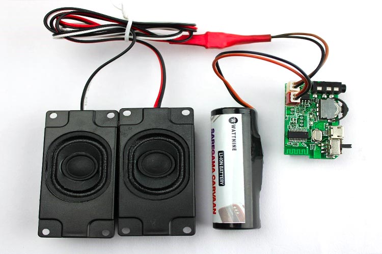
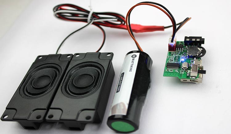
For those who love tinkering with electronics, making a Bluetooth speaker from scratch can be a satisfying and a fun experience. In this article, we'll learn step-by-step guide on how to build your very own wireless Bluetooth speaker using basic electronic components under 9$ or 700rs. We have previously built many audio related projects using various amplifiers, follow the link to learn more.
Materials you’ll need:
Bluetooth audio receiver
Amplifier
Lipo battery
Switch
TP0456
Acrylic laser-cut parts
Some wires
A soldering iron
A hot glue gun
Before we dive into the step by step process. Let’s understand working of some of the important modules which are necessary to build this speaker
Bluetooth Audio Receiver 3.0 Module
The Bluetooth audio receiver module can receiver audio signal wirelessly from source and then can send output directly (for low watt speakers) or to the amplifier (for high watt speakers).
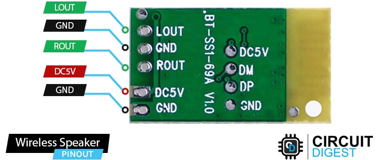
The input is received through Bluetooth and then these signals are sent to LOUT and ROUT pins as output. This module needs to be powered through a 5V DC power supply.
Pinout of Bluetooth 3.0 Audio Receiver Module
LOUT Left audio output. This pin provides the left audio channel output from the module.
ROUT Right audio output. This pin provides the right audio channel output from the module.
DC5V 5V Power supply input pin for the module
GND Ground pin for the module.
PAM8403 Amplifier Module
The PAM8403 is an audio amplifier module. Amplifier is a device which is used to convert weak signals into strong signals i.e increase the magnitude of the signal.
In our use case, the amplifier module is used so the input received from the Bluetooth module can be amplified and thus sent to the speakers through left and right channel output.
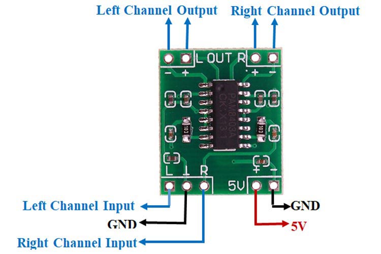
Pinout of PAM8403 Amplifier Module
VCC Power supply pin for the amplifier module. Connected to the positive terminal of the power source (5V) or voltage regulator.
GND Ground pin for the amplifier module. Connected to the negative terminal of the power source and ground reference.
LIN Left channel input. This pin receives the audio signal for the left audio channel.
RIN Right channel input. This pin receives the audio signal for the right audio channel.
GND Ground pin for the audio input signals. Connected to the ground reference of the audio source.
LOUT+ Positive left channel output. This pin provides the amplified positive signal for the left audio channel.
LOUT- Negative left channel output. This pin provides the amplified negative signal for the left audio channel.
ROUT+ Positive right channel output. This pin provides the amplified positive signal for the right audio channel.
ROUT- Negative right channel output. This pin provides the amplified negative signal for the right audio channel.
Circuit Diagram of PAM8403 Module
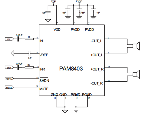
The PAM8403 is an audio amplifier module that can amplify sound signals to drive speakers. It is a 2-channel amplifier, which means it can handle both left and right audio signals. The module has a power supply pin (VCC) and a ground pin (GND) to provide the necessary power for the amplifier to work.
To connect audio signals, there are two pins called INL and INR, which stand for left and right channel input. These pins receive the audio signals from your audio source, like a smartphone or computer. To improve the audio quality, it is recommended to connect a small capacitor (0.47µf) between these input pins and the ground. This helps reduce any unwanted noise that may come from the power supply.
The amplified audio signals are then sent to the speakers. The module has four output pins: ± OUT_L and ± OUT_R. The positive side of the left channel connects to the + OUT_L pin, and the negative side connects to the - OUT_L pin. Similarly, the positive side of the right channel connects to the + OUT_R pin, and the negative side connects to the - OUT_R pin.
One of the advantages of the PAM8403 is that it doesn't require additional low-pass output filters. This means it can directly drive the speakers without the need for extra components, making it more efficient compared to other amplifier types. The recommended operating voltage for the PAM8403 is 5.5V, so you should provide a power supply that matches this voltage to ensure proper operation.
Commonly asked questions about amplifier modules
What is the use of PAM8403 amplifier module?
The PAM8403 amplifier module is commonly used to amplify audio signals and drive speakers in various applications. It is particularly popular in portable audio devices, such as Bluetooth speakers, MP3 players, and small audio systems. Its compact size, efficiency, and filterless architecture make it suitable for low-power audio amplification needs.
Difference between class:- A, B, AB and C amplifiers
Different amplifier classes refer to the way the amplifiers operate and their efficiency. Class A amplifiers have high-quality output but lower efficiency as they continuously consume power. Class B amplifiers use two transistors to amplify positive and negative halves of the input signal, resulting in better efficiency but with some distortion at the crossover point. Class AB amplifiers combine characteristics of Class A and B amplifiers, aiming for both decent quality and improved efficiency. Class C amplifiers are highly efficient but not suitable for audio due to their high distortion, mainly used in radio frequency (RF) applications.
What are the different types of amplifiers according to their use case?
There are several types of amplifiers based on their use case, including:
Audio Amplifiers: Used to amplify audio signals for speakers or headphones, ranging from small audio devices to home theater systems.
Instrument Amplifiers: Specifically designed to amplify electric musical instruments like guitars, keyboards, and basses.
RF Amplifiers: Used in wireless communication systems and RF devices to amplify radio frequency signals.
Operational Amplifiers (Op-Amps): Widely used in electronic circuits for various applications, such as amplification, signal conditioning, filtering, and mathematical operations.
Power Amplifiers: Designed to amplify high-power signals, typically used in large sound systems, PA systems, and concert venues.
Differential Amplifiers: Used in communication systems, audio equipment, and measurement instruments to amplify the difference between two input signals.
These are just a few examples, and there are many other types of amplifiers catering to specific applications and requirements.
Now that we are done with the theory let’s start building this project Step by Step
Create Speaker Enclosure
The first step in building your wireless Bluetooth speaker is to create the speaker enclosure. You can use any material you like, but we used acrylic.
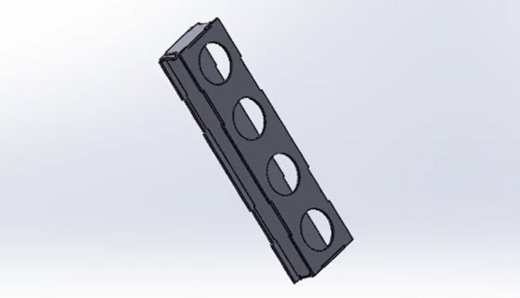
To make this first, you need to use solidworks and create the design for the speaker. Then the next step is to cut them through a laser cutting machine (if you own one or through nearby shop)
After laser cutting the parts will look like this.
Assembling Front Plate
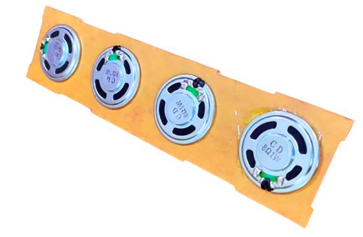
Next thing you need to do is attach the speakers to the front plate of the laser-cut parts just attach some glue to the front plate and connect the 4 speakers to it.
Back Cover
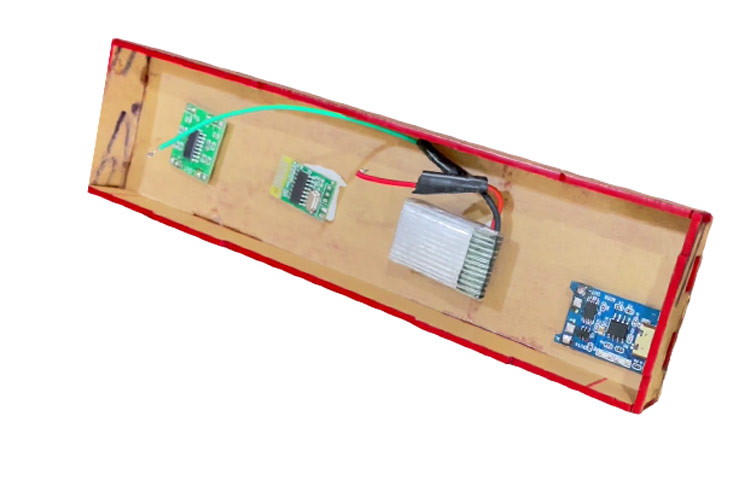
Take the back cover and attach the supporting side structures to it.
First attach the amplifier, Bluetooth module and the battery to the back plate.
When that is done. You can attach the TP0456 charging module and the switch.
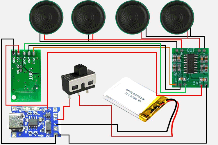
Circuit Diagram of Wireless Bluetooth Speaker
You can refer to the above circuit diagram to recreate your project. It’s simple to follow.
Final Assembly and Testing
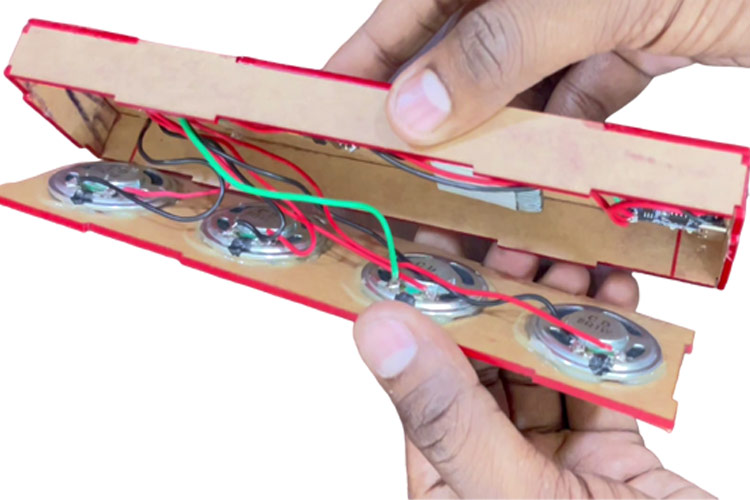
When that is done, you can connect the front and back panel and then glue it.
Remove the paper layer of the acrylics to get an amazing final look.
Congratulations, you've just built your own wireless Bluetooth speaker! To use it, simply turn on your Bluetooth-enabled device and pair it with the speaker. You should now be able to enjoy high-quality sound from your new DIY speaker.
In conclusion, building a wireless Bluetooth speaker is a fun and rewarding project that anyone can do with some basic electronic components and a little bit of know-how. Just follow the steps outlined above, and you'll be on your way to enjoying your very own homemade speaker in no time!
Imagine immersing yourself in the rhythm of your favorite music while being surrounded by a dazzling display of colorful lights that dance in sync with every beat. In this blog, we will explore how to build an Arduino-powered Bluetooth speaker that not only delivers impressive sound but also features reactive NeoPixel LEDs that respond to the music. Get ready to bring your music listening experience to a whole new level of audiovisual delight!
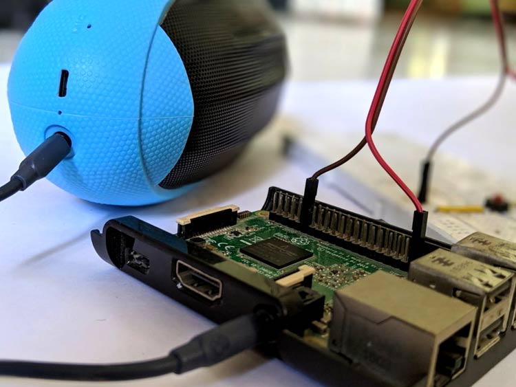
Tired of being tied down by cables while listening to your favorite music? In this blog, we'll explore how to transform your Raspberry Pi into a Bluetooth speaker, allowing you to wirelessly stream audio from your smartphone, tablet, or any Bluetooth-enabled device. Say goodbye to tangled wires and embrace the convenience and freedom of a Raspberry Pi Bluetooth speaker setup!
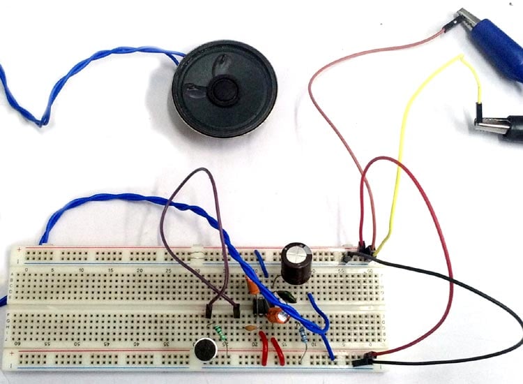
Are you looking to amplify the sound from a microphone and directly drive a speaker? In this blog, we'll guide you through the process of building a straightforward microphone-to-speaker amplifier circuit. With just a few components and minimal soldering skills, you can create an amplifier that will enhance the audio captured by a microphone and produce louder output through a speaker. Let's dive in and get started!
The increase in requirements for highly fuel-efficient, lower-emission two-wheelers is driving internal combustion engine designers to switch from carburetor-based air-fuel mixing to electronic fuel injection (EFI) systems. Designers are now challenged to find cost-effective solutions that solve the challenges of fast startup and enable reliable operation of EFI systems. This article discusses the challenges that two-wheeler designers face when switching to an EFI system, notably a 100 ms fast startup requirement. A reliable, efficient, cost-effective solution that enables quick flow of fuel to achieve the desired startup is presented. By enabling simplified designs that achieve fast startup, simplify bills of materials (BOMs), and facilitate electromagnetic-compatibility (EMC) compliance, the solution presented can improve reliability and shorten research and development time in two-wheelers.
Basics of Fuel-Mixing Systems
In an internal combustion engine, proper mixing of fuel and air in specified proportion is critical for efficiency and reliability. Low-cost two-wheelers have commonly used carburetor-based fuel mixing, but—to meet new carbon emission standards—they are being phased out in favor of the efficiency offered by EFI methods.
Carburetor systems mix air and fuel for combustion using mechanical parts, such as the fuel float chamber and the throttle venturi as well as fuel jets that spray fuel and mix it with incoming air. When the throttle of the vehicle is opened, air flow through the carburetor increases, and the venturi effect causes fuel to enter the chamber. As air flow increases, air suction increases, as does delivery of fuel, resulting in increased vehicle acceleration.
An EFI system integrates a high-speed brushless DC (BLDC) motor controlling a fuel injector that delivers fuel to the engine. An EFI system consists of electronic sensors and a fuel pump that delivers fuel to the combustion chamber located inside the fuel tank of the vehicle. The fuel supply to the combustion chamber is governed by an electronic control unit (ECU) that constantly monitors the fuel supply and precisely controls the ratio of the fuel flow based on the engine requirement. The ECU uses various parameters—throttle position, engine speed, engine temperature, and engine load, among others—for the precise and efficient control of fuel injection directly into the combustion chamber of the cylinder. A basic block diagram of an EFI system is shown in Figure 1.
Figure 1: Block diagram of an EFI system.
The fuel pump in an EFI system draws fuel out of the fuel tank and provides it to the fuel injectors via multiple stages, as shown in Figure 1. This pump is generally driven by a BLDC motor because of its reliability, high power density, high efficiency, lower noise, lower electromagnetic interference (EMI), lower maintenance requirement, and longer life span. Unlike the traditional brushed DC motors that use brushes to transfer electrical current to the rotor, BLDC motors have permanent magnets on the rotor and electromagnets on the stator, allowing for a more efficient transfer of energy. Commutation of a BLDC motor is achieved electronically based on the instantaneous rotor position. Some systems use rotor alignment, but sensorless control of the BLDC motor system is preferred for greatest reliability.
Comparing Carburetor-Based and EFI Solutions
The traditional mechanical design of carburetor systems is very rugged. However, the air-fuel mixture cannot be accurately controlled, which leads to less fuel efficiency and increased emissions. Performance is also affected by ambient conditions, such as temperature. Maintenance (cleaning, adjustment, and tuning) is frequently required in a carburetor-based system, albeit this maintenance can be performed quickly and at low cost.
EFI systems are more accurate in the air-fuel-mixture ratio for a given driving condition and provide cleaner and more-efficient combustion. Also, throttle responses are quicker, and fuel economy is much better. Moreover, EFI systems are less prone to damage and therefore are generally maintenance free. However, EFI systems are typically perceived to be expensive compared to conventional carburetors, and tuning of fuel injection systems through ECU mapping is complex, which increases the cost when maintenance is needed.
Carburetor-based and EFI solutions are compared in Table 1. As two-wheeler manufacturers make the switch to EFI systems to meet new emission standards, designers are now looking to balance the new associated tradeoffs.
Comparison of Carburetor-Based System and EFI System
Attributes
Carburetor-Based System
Electronic Fuel Injection System
Versatility
Air-Fuel Mixing
Crude
Precise
Combustion
Less Efficient
More Efficient
Emission
High
Low
Mileage
Fuel Efficiency
Low
High
Performance
Throttle Response
Slow (Lag)
Faster
External Factors
Highly Impacted
No Impact
Tuning
Process
Manually
Via ECU Mapping
Easiness
Easy and Quick
Complex and Sluggish
Maintenance
Dust Impact
High Probability
Less Probability
Requirement
Frequent
Rare
Complexity
Easy (Outside Engine)
Difficult
Cost
Low
High
Cost
Overall Cost
Less Expensive
More Expensive
Speed, Efficiency, Reliability, and Ease of Tuning
Quick fuel delivery in a kick-start system critically requires quick BLDC motor startup. The efficiency of the overall system is crucial in the design. Because the device temperature is directly proportional to the power loss, minimizing power losses in the motor driver IC is also crucial. These requirements present fuel pump challenges that require an understanding of fuel pump operation.
Fuel-pump startup time—from zero to full speed—typically must be as little as 100 ms. During this time, the BLDC motor must complete either a rotor alignment cycle or an initial position detection (IPD) sensorless starting cycle plus a transition to the sensorless mode. The required fast and reliable startup of a sensorless BLDC motor requires a driver that can perform the rapid IPD cycle within these requirements.
While there are many solutions available on the market today, the Allegro A89303 three-phase sensorless BLDC motor driver IC purpose-designed for fuel pump application is a fast, efficient, reliable option. An Allegro-proprietary sensorless startup algorithm is incorporated that uses a trapezoidal drive algorithm to minimize time to ramp-up to maximum speed. It ensures fuel-pump startup to full speed in typically 50 ms, as shown in Figure 2. A two-pulse IPD algorithm ensures reliable and accurate initial position detection—with low resolution (30 degrees) in fast detection time (see the A89303 product datasheet)—and assists in reducing the overall startup time of the BLDC motor. An overlapping mode adaptively adjusts (leads) the phase angle of the applied voltage. This phase leading allows efficient operation of the BLDC motor and maximizes the extraction of power from the BLDC motor. These features enable easier startup and smooth, responsive, efficient operation of kick-starters.
Figure 2: Starting of a fuel pump BLDC motor with A89303.
To meet the goals of the industry, the device needs to allow for easy tuning and protection against various fault scenarios. Many applications also require detailed diagnostics of faults. In addition to in-housing many advanced features that improve overall motor-drive efficacy—including a low on-state resistance (RDS(on)) MOSFET power stage, integrated charge pump, and I2C communication block set—the highly integrated A89303 motor driver provides fault reporting against various unwanted scenarios—such as overcurrent (motor phase short), overvoltage, undervoltage, charge-pump undervoltage, lock detection, and thermal shutdown. To allow the tuning of various electrical parameters, the I2C registers enable detailed diagnostics to be read and the I2C interface allows for ease of programming. In total, the A89303 delivers the speed, efficiency, reliability, and ease of tuning demanded by the two-wheeler industry.
Reliability with EMC Compatibility and Design Simplification
Although many motor driver ICs may be available to satisfy speed, efficiency, and tuning challenges, they typically come with significant additional development time and cost for EMC compliance, as well as complexity that reduces reliability.
Integrated devices are subject to EMI. Driver designs that place capacitor(s) and regulator(s) outside of the IC create a high-frequency emission source that results in EMI. To mitigate this noise, additional components, such as beads, are often required for EMC compliance. This is especially true in high-frequency-switching applications, such as motor drivers for fuel pumps. The additional components lead to larger, complex designs with increased development time and increased points of potential failure.
Considering the EMI challenges that arise with EFI systems, a fast, reliable, cost-effective solution likely means one that minimizes sources of high-frequency noise and facilitates EMC compliance such that development schedules are reduced, BOMs are reduced, and commensurate savings are gained.
The Allegro A89303 addresses this need by in-housing the capacitor of the internal regulator, which bypasses the high-frequency switching noise of the internal digital circuitry. A spread spectrum clock in the device also minimizes EMI by spreading the emission. By bypassing and spreading the high-frequency-switching noise, systems that integrate the A89303 can earn extra margin to facilitate EMC compliance and accelerate development schedules.
BLDC motor driver operation using the A89303 requires only six passive components, as shown in Figure 3. By minimizing the number of additional components using a compact device size—the A89303 is available in the small 6.5mm x 4.4 mm thin-shrink small-outline package (TSSOP) and the smaller 5 mm x 5 mm quad-flat no-leads (QFN) package—a smaller PCB can be used to realize a smaller, more-efficient, cost-effective solution.
Figure 3: Low component count for the A89303 device.
The High-Performance, Cost-Balancing Solution
To meet changing emission standards, many two-wheeler system designers now face the need to switch from carburetor-based systems to EFI systems. Many purpose-designed features make the Allegro A89303 motor driver IC an ideal solution for fuel pump applications, including fast and accurate startup, efficient optimization, integrated protection features, fault handling, and ease of programmability.
EVs are expensive compared to ICE vehicles because of the battery cost. The EV battery cost makes up 60% of the total EV price. Therefore, to compensate for the high price of EVs, the automakers add features and functionalities to present them as differentiating factors to the buyers. These features generally aim to provide safety and convenience to the driver.
Arduino is a very popular open-source platform and Arduino UNO is one of the most loved microcontrollers among electronics hobbyists worldwide. It consists of a physical programmable circuit board and an Integrated Development Environment (IDE) that allows the writing and upload of computer code to the board very effortlessly. Due to its user-friendly environment and huge community support, it become the first choice for beginners in this field.
In this article, we will go through some of our best Arduino UNO projects that you can make at home easily and understand the functions and workings of Arduino UNO. All the Arduino project ideas listed below were built on Circuit Digest and you can get them complete code and circuit for all projects completely for free by just clicking on the respective links. That being said let's get started with this article.
1. Building your own Sun Tracking Solar Panel using an Arduino:
Traditionally, solar panels are fixed and the movement of the sun over the horizon means that the solar panel does not harness maximum energy most of the time.
This arduino UNO project introduces a Sun-tracking system project using an Arduino Uno,a servo motor, and LDRs to optimize solar panel efficiency. Hardware components, circuit connections, and assembly instructions are provided, along with step-by-step code explanations for the project. The project concludes by emphasizing the practical applications of the system and potential enhancements for larger solar panels.
2. Bluetooth Controlled Pick and Place Robotic Arm Car using Arduino:
This fun arduino project outlines the construction of a Bluetooth-controlled robotic arm using an Arduino board and servo motors, emphasizing precision-controlled movements in robotics.
It provides insights into the arm's kinematics and the significance of understanding forward and inverse kinematics equations. The Arduino tutorial highlights the assembly process, circuit connections, and code implementation, emphasizing the role of servo motors and the Android application for wireless control. Overall, the project serves as an educational introduction to robotics and automation, showcasing the fusion of hardware and software in creating a versatile and interactive mechanical system.
The Arduino Smart Dustbin Project is an innovative solution for waste management,utilizing an Arduino Nano, servo motors, an HC-SR04 ultrasonic sensor, and an IR sensor.
The project's objective is to automatically open the lid upon detecting nearby objects, promoting cleanliness and sanitation. The circuit design emphasizes proper voltage regulation through a buck converter, ensuring the system's stability. The code involves monitoring sensor inputs and controlling servo motors to facilitate smooth lid movement. Overall, the project aligns with the "Swatch Bharat Mission," encouraging a clean and eco-friendly environment through hands-free waste disposal.
4. DIY Arduino Bluetooth Car Controlled by Mobile Application:
If you are a beginner and enjoy building robots, this is likely the first Arduino project you will do after learning the basics, which is why we decided to build a Wireless Bluetooth Controlled Robot Car Using Arduino.
The Wireless Bluetooth Controlled Robot Car is a beginner-friendly Arduino project with an Android app for control and RGB Neopixel LEDs. It requires components like Arduino UNO, HC05 Module, L298N Motor driver, NeoPixel LEDs, etc. The onboard chassis building process and motor connections are detailed..The Arduino Project code utilizes SoftwareSerial.h for Bluetooth communication and controls robot movements and LED lights. The Android app, built with MIT app inventor, enables users to send commands to the robot via Bluetooth.
5. Build your own Mars Rover Robot using Arduino:
This cool looking Arduino Project presents the construction of an Arduino-based Mars rover, emphasizing design, components, and assembly. It highlights the role of the L298N motor driver and HC-05 Bluetooth module in movement and control.
Detailed circuit diagrams and code explanations aid technical understanding, with an Android app enabling rover control. The project encourages exploration in robotics, electronics, and programming, fostering curiosity and creativity in space exploration. The planet Mars has captivated our imagination for centuries, and the idea of sending rovers to explore its surface has fueled our curiosity even further.
This Arduino Project is not for beginners as it outlines the construction of a self-balancing robot using an Arduino, including component selection, 3D printing, and assembly.
It covers the circuit diagram and the PID algorithm's implementation for achieving self-balancing, emphasizing the significance of tuning PID values. The guide provides troubleshooting tips and instructions for ensuring the project's success. This way I would be able to grasp the underlying concept behind all these scooters and also learn how the PID algorithm works.
7. Building an easy Line Follower Robot using Arduino Uno:
The Line Following Robot (LFR) is quite an interesting Arduino project to work on! In this tutorial, we will learn how to build a black line follower robot using Arduino Uno and some easily accessible components.
The Line Follower Robot (LFR) uses IR sensors to follow lines on the ground autonomously, navigating with four actions: forward, left turn, right turn, and stop. The project requires an Arduino Uno, an L293D motor driver, IR sensor modules, a battery, BO motors, and a hobby robot chassis. The circuit integrates sensors, motor driver, motors, and Arduino, with the motor driver ensuring proper motor control. The code uses basic Arduino functions to define the robot's actions based on sensor outputs. Calibration involves adjusting the IR module's variable resistor, ensuring accurate line detection. Detailed assembly instructions and a video demonstration are provided for the project.
8. DIY Arduino Based Color Sorter Machine using TCS3200 Color Sensor:
The color sorting machine employs a TCS3200 color sensor, Arduino UNO, and servo motors for automated color-based sorting of objects into designated boxes.
Its applications span diverse industries like agriculture, food, and mining where color identification is essential. The project involves building a robotic arm using a Sunboard sheet, and the program logic utilizes the servo library and a detectColor() function to determine and sort colors. Detailed step-by-step instructions and a video demonstration are provided for reference. Some application areas include the Agriculture Industry (Grain Sorting on the basis of color), the Food Industry, the Diamond and Mining Industry, Recycling, etc.
9. Human Following Robot Using Arduino and Ultrasonic Sensor:
This Arduino UNO Project is not only fun to build but also is really exiting to watch it work. One exciting application of robotics is the development of human-following robots.
This article presents the development of a human-following robot with Arduino and three ultrasonic sensors, highlighting its advantages over conventional designs. It outlines the necessary components and the circuit diagram, emphasizing the crucial connections required for the project. The Arduino code demonstrates how the robot functions based on the input from the sensors, enabling it to measure distances and adjust its movements accordingly. The article underscores human-following robot's versatility and potential applications, citing their relevance in various sectors such as retail, security, entertainment, and elderly care.
10. Automatic Irrigation System using an Arduino Uno:
This Arduino UNO project details the creation of an Automatic Irrigation System using an Arduino Uno and a soil moisture sensor.
The sensor measures soil moisture, triggering the water pump when levels are low and stopping it when the soil is adequately hydrated. A relay module facilitates pump control, while a 5V battery powers the circuit. The code, without libraries, reads sensor data, converts it to a percentage, and operates the pump based on predefined moisture thresholds. The guide includes a circuit diagram, assembly steps, and calibration instructions, making it accessible for beginners.
In an effort to reduce dependence on Asian countries on chip import and to revive the country’s growth in semiconductor production, the USA in August 2022, has unleashed the much-awaited CHIPS Act worth $52 billion. Since the time of Trump administration the country has been undertaking various strenuous efforts and involved in geopolitical scuffles with China to shatter the latter’s dream of leading the technology industry. The US is trying to persuade its EU allies and India to join its league of anti-China strategies and decided to craft a ‘Chip 4’ association with Taiwan, South Korea, and Japan to build a strong semiconductor supply chain that will keep out China.
In the last two decades, the share of US chip manufacturing has reduced drastically, while advanced chipset production is now largely spearheaded by a couple of countries like South Korea and Taiwan. Currently, 90 percent of the sophisticated chips, which are of great importance for the US defense and economy are manufactured in Taiwan. This has created worries about the supply’s vulnerability, given China’s plan of military invasion on Taiwan. Chipsets, which are less sophisticated but useful in electronics, cars, and other products are now produced in China whose market has also augmented exponentially. 12 percent of semiconductors are now produced in the US that are not globally advanced.
Senior Research Analyst Faisal Kawoosa, founder of techARC, told CircuitDigest, “The closure of factories during the surge of the coronavirus pandemic has created huge disruptions on supply chains and also the winter storm in Texas further damaged the country’s manufacturing cluster. Now, demand suddenly soared unexpectedly as government offices, educational institutions, and corporate offices began work from home. Therefore, the chip shortages increased and the GDP also witnessed a sharp cut in percentage. The lockdown situations in the past few years has made absolutely clear that semiconductors play an important role in today’s world economy, and the costs that accompany restricted the supply.”
It is now clearly evident that the CHIPS and the Science Act, which was unveiled after several rounds of heated discussions, might not likely work the way it was intended. The scheme, which was unleashed with bipartisan support, was meant to boost the in-house chip manufacturing units. Even though the US is one of the leaders in advanced semiconductor design, its share of international chip production slumped 37 percent in 1990 to 12 percent currently. While speaking of the imperativeness of such technology in terms of national security, the US defense department requires 1.9 billion of them a year.
Funding For Semiconductor Manufacturing-US
The problem is now manufacturing chips in US consumer 25 percent longer duration and 50 percent more expensive than doing such in Asia. The domestic semiconductor manufacturers are now facing serious hurdles mostly due to government negligence, claim experts. According to a Bloomberg report, the red tape is a major impediment because from 1990 until 2020, the duration required to build new fabs increased by 38 percent. For instance, the Clean Air Act takes more than one and half years to give permission. Then, the review by the National Environmental Policy Act takes more than four and half years. A lot of unimportant federal laws will suddenly appear on the way and a lot of agencies must be consulted to approve the project.
Analysts told Bloomberg that such hold ups creates no confidence among private investment, increases project costs, and seriously restricts US manufacturers from competing in the international market.
Another grave hurdle is that the country does not have sufficient skilled workforce required for this sector, which researchers feel that the broken immigration system of late is responsible. A survey report highlighted that around 300,000 more skilled workforce is required to complete the ongoing fab ventures, leaving out the new ones, claims Bloomberg. Although TSMC and Intel announced their new projects in the country they are facing a lot of challenges to find proficient workforces for the same.
Most of the experts believe that these problems can be solved easily. For instance, there is a requirement to deploy fast track exemptions for semiconductor makers under the federal environment laws or better modify the law to give momentum to all such ventures and impede shallow laws. Visas must be escalated for proficient workforce, prioritize applicants with needed STEM abilities, and also increase green card allotments for foreign degree holders.
According to the market experts, various strategies can be formed and deployed in an effort to achieve chip sovereignty via the CHIPS act, but if the SMBs are not included then surely the act will fail to boost the chip economy in the country. The president has recently proclaimed who would lead the country’s export council where national security experts and CEOs of global firms were asked to spearhead, but not a single SMB company name was mentioned. According to a report by fortune.com, around 64 percent of new employment is generated by SMBs that contribute to 99.9 percent of overall trade in the US.
It is a clear fact that most of the subsidies and funding from the act will be benefited by the global companies and therefore, a sufficient percentage of the fund must be allocated to the small businesses to provide momentum in materials science, packaging, and mechanical design. The US government has called for the imperativeness of public-private partnerships, but at the same time, it is also important to have strategic alliances between MNCs and SMBs.
Now, when the CHIPS Act was finally unleashed, the government understood that the supply of nation’s chips that powers most of the electronic products from smartphones, washing machines, and cars to supercomputers, and defense products, faced a huge impediment at a difficult situation. For the manufacturing of sophisticated chips, the US is mostly relied on Taiwan. Now, geopolitical scuffles with China, the possible tussle in the South China sea as well as between North Korea and South Korea giving a blow to the semiconductor supplies and therefore, the US government was convinced about increasing the economy of the country’s chip manufacturing. But, with a couple of red tapes, and huge workforce expenses, the chip manufacturers require additional incentives to bring out the transformation.
Matthew Orf, Research Analyst with Counterpoint Technology Market Research, said "When the CHIPS act was finalized, around $200 billion worth of investments have been proclaimed to increase the chip production facilities. A couple of bigger firms like Texas Instruments, Intel, TSMC, Samsung, and Micron have announced their investments to create new foundries. Although the act has sparked private players to begin new projects, some of the shortcomings and legislations of the provisions could make it a challenging task. This is mostly because the new ventures are furnished with a lot of regulations and red tape that could cause the projects to stop for a while. Even though the funding has been allocated for job training and workforce education, the volume of the requirement of new employees, and the lack of skilled workforce will make the dream of the country of leading the semiconductor industry more difficult.”
“Most importantly, the act failed to find out the possible causes why exactly the country’s semiconductor industry weakened, mostly manufacturing. Experts believe that stern regulations and workforce costs makes manufacturing in the US more intricate than the Asian countries. Now, the problem is if the funding remains dry, how will the nation’s semiconductor industry remain globally competitive?,” added Work.
For the past few years, developing countries like India are going through a lot of alterations in terms of technology and one such development in this world is robotics. Now, with a huge improvement in science and technology, robotics is appearing in the industrial space very quickly. Experts opine that robotics is very useful for industrial automation that includes assembly, manufacturing, and packaging.
The pace and variety of electrification across many aspects of our daily lives continue, driven by the convergence of multiple factors. These include increased renewable sources such as solar power from photovoltaic panels and wind power via large turbines paired with higher-density, lower-cost rechargeable batteries for storage, sophisticated battery-management systems to monitor their charging/discharging, and inverters to convert the stored energy into usable power.
We’re seeing a wide span of applications, from highly visible grid-scale installations and medium-size office and residential applications to increased adoption of electric vehicles (EVs) and their chargers (Figure 1) and even less visible roles such as propane-free industrial forklifts. The size and scope of these systems range from wide-scale and regional to highly focused and localized.
Figure 1: This row of electric vehicle charging stations is evidence of the further penetration of electric power in daily life and the associated challenges. (Source: Noel - stock.adobe.com)
The Challenge is in the Details
Regardless of the size or scope of a project, there’s one truism that every engineer with any real-world experience knows: It is the less-visible and less-glamorous components that often make the difference between a system that works to some level but has multiple shortcomings and performance issues, versus one which is solid, tight, reliable, and also meets the many safety and regulatory standards governing its operation.
Components with precise functions—such as solar panels, windmill turbines, battery management systems (BMS), and power inverters—get much of the design effort and attention. The public even recognizes them to some extent due to their high profile. Nonetheless, the reality is that many more “smaller” components are needed for a complete and properly functioning system. For example, in addition to the major blocks of a modest solar-inverter installation (Figure 2), smaller and critical functions are needed.
Figure 2: A basic solar-inverter installation has large functional blocks and smaller yet vital functions. (Source: TE Connectivity)
Two of these are:
Contactors (orange circle 3) are high-capacity, electrically controllable on/off switches (similar to a relay) used for power distribution, main switch functions, and overall control. The contactor makes it possible to switch and control power paths.
EMI filters (orange circle 4) provide needed attenuation of common mode and differential mode interference and electromagnetic interference (EMI), which is unavoidably created by the switching power inverters. Without these filters, the Battery Energy Storage Systems (BESS) create excessive interference, which affects not only its operation but nearby systems as well and will also likely fail certification to regulatory limits.
Size, Materials Must Scale
While these contractors and filters have schematic diagrams and functions similar to their counterparts in the low-power system, the similarities end there (Figures 3 and 4).
Figure 3: The contactor is an electrically controllable high voltage/current switch, similar to a relay, used to route power. (Source: Mouser Electronics)
Figure 4: EMI filters are offered in dual- and single-stage configurations and are essential for attenuating common- and differential-mode interference and electromagnetic interference (EMI). (Source: Mouser Electronics)
The components must be physically more significant, have more robust internal and external contacts and connections, use different materials and contact plating, and be suitable for rugged handling and exposed installations. Due to the higher voltages and currents, there are concerns related to contact erosion, localized heating, and high-voltage flashover and sparking, which could degrade performance or cause outright failure.
A closer look at a contactor and a filter provides a sense of these functions in higher-power applications.
The ECK150/200/250 series of high-voltage DC contactors from TE Connectivity (TE) is designed for control in EV charging stations, solar inverters, battery energy storage systems, automated guided vehicles (AGV), and battery-powered forklifts (Figure 5). The units can be used for DC breaking voltage at 1000VDC and breaking current of 2000A (both maximums) with a continuous carry current of 250A.
To achieve this performance, they are packaged in hermetically sealed cylindrical enclosures using ceramic technology, making them safe and reliable.
Figure 5: The ECK150/200/250 series of high-voltage DC contactors use ceramic-sealing technology for reliability under challenging conditions. (Source: Mouser Electronics)
The contractors are 52 millimeters long with a 56mm diameter while meeting all relevant UL, CE, and CCC approvals. As a further benefit, the built-in pulse-width modulated “economizer” activator means that the required contactor hold power is just 1.7W despite the high voltage/current ratings, which minimizes wasted energy and thermal dissipation.
The Corcom AHV series of Three-Phase High-Performance EMI Filters, also from TE Connectivity, are modules with a rated voltage of up to 760VAC and a current rating of up to 1000A. They feature a single- or dual-stage delta configuration in a compact bookshelf or chassis design, along with a small footprint to save space and costs (Figure 6); the smallest unit (7A) measures approximately 300mm deep × 140mm high × 70mm wide while the corresponding dimensions of the largest unit (180 A) are 310 × 265 × 165mm.
Figure 6: The Corcom AHV series of Three-Phase High-Performance EMI Filters are available in single- or dual-stage models to provide different levels of noise attenuation. (Source: Mouser Electronics)
They are well suited for renewable-energy converters/inverters, EV charging facilities, and other industrial equipment and devices. They are available in single- and dual-stage configurations to meet the required EMI suppression goals. For example, the 75-A single-stage bookshelf unit with terminal block input and output has these common-mode and differential-mode insertion losses in dB (Figure 7):
Figure 7: The common- and differential-mode attenuation (in dB) from 0.01 to 30MHz for a 75A, single-stage Corcom AHV-series filter is high. (Source: TE Connectivity)
In contrast, the corresponding 75A dual-stage bookshelf unit has somewhat higher attenuation for both modes across all frequencies (Figure 8).
Figure 8: If the attenuation provided by a single-stage unit is insufficient for the system or regulatory mandates, the dual-stage unit adds another approximately 10 to 20dB across the same frequency spectrum. (Source: TE Connectivity)
Conclusion
While the higher-profile functional blocks of a BESS or more minor system are critical, it’s important for designers also to pay attention when selecting passive, less-visible components such as contactors, EMI filters, and even connectors. Choosing devices that don’t have the needed ratings or mechanical or electrical, mechanical, or environmental ruggedness leads to immediate performance shortcomings, regulatory issues, and short- and longer-term reliability concerns. TE Connectivity offers a full range of products, in a wide selection of ratings and form factors, to meet these needs and fill in the large and small pieces for successful energy-storage and -delivery systems.
Bill Schweber is a contributing writer for Mouser Electronics and an electronics engineer who has written three textbooks on electronic communications systems, as well as hundreds of technical articles, opinion columns, and product features. In past roles, he worked as a technical website manager for multiple topic-specific sites for EE Times and as the Executive Editor and Analog Editor at EDN.
He has an MSEE (Univ. of Mass) and BSEE (Columbia Univ.), is a Registered Professional Engineer, and holds an Advanced Class amateur radio license. Bill has also planned, written, and presented online courses on a variety of engineering topics, including MOSFET basics, ADC selection, and driving LEDs.
Over the past few years, electric vehicles have now appeared as a pivotal point of realizing environmental policies all through the globe. In order to meet the same, the automobile manufacturers have realized that their future products will be crafted outside the ecosystem of conventional internal commercial engines (ICE). Hence, their business models and strategies are being tweaked to go ahead with the time. For electric cars, the most crucial and expensive component is the battery and the competition rat-race is escalating among OEMs and battery makers all over the world to strengthen its foothold in the EV battery market. The positive aspect is that this rat-race is opening the gate for emerging and cutting-edge technologies.
Now, in the automobile industry, lithium-ion batteries have gained more traction than the other ones, which is simply because of the fact that in a very small package, these batteries have the potential to collate huge amounts of energy. In the past few years, more innovative battery technologies are being developed and researched to replace the lithium ones in terms of sustainability, efficiency and cost. Experts state that most of the new battery technologies are not transforming the diaphragm when it comes to energy storage and powering devices. The biggest reasons why researchers are carrying out research on new technologies are mostly associated with safety like fire danger, and the sustainability of the materials utilized in the manufacturing of lithium-ion batteries, like magnesium, cobalt, and nickel.
Researchers have also added that there has been a massive improvement in the making of lithium-ion batteries and other battery technologies. Therefore, let’s find out below some of the upcoming battery technologies waiting to appear in the global EV market.
NCM 811
The energy density of lithium-ion batteries needs to be enhanced and therefore, battery-makers are investing largely on R&D and although the momentum of the improvements has been a bit slower, but lithium-ion batteries have helped in augmenting the speed and range of EVs with the help of high-energy source materials and also developing the per-unit cell size. On the other hand, various efforts have been undertaken to increase the nickel portion of total cathode materials. Earlier, many of the large battery makers have proclaimed to launch NCM 811 by 2019-2020, claims Counterpoint Research. Most importantly, NCM 811, which is equipped with 80 percent nickel, 10 percent cobalt and 10 percent manganese has a larger longevity and offers EVs with longer range on a single charge, claims Counterpoint Research. Battery manufacturer AESC announced that they are manufacturing NCM811, which promises more than 300Wh/Kg and 600-650Wh/L in 2020.
Solid-State Batteries
These batteries utilize a solid electrolyte other than a gel or liquid electrolyte. The solid electrolytes are mostly a solid polymer, ceramic, glass crafted with sulphites. This year, global auto firm BMW announced that it will commence testing solid-state batteries for its utilization in the EVs, which will be manufactured by Solid Power. PCMag claims that these batteries are now already being utilized in some smartwatches and pacemakers. These batteries, when compared to lithium-ion, pack more power and are also more efficient. Therefore, the batteries used in EVs could be charged faster, compact in size, weigh less,and escalate driving range. Some media reports highlighted that solid-state batteries have more longevity with seven times more charging capacity. Most importantly, they are safe to operate because the solid electrolytes are fireproof. CNBC reported that these batteries could be used in EVs in early 2024.
Lithium-sulfur Batteries
In this technology, the battery’s cathode utilizes sulfur, which is more sustainable than cobalt and nickel mostly found in the anode with lithium metal. The US based battery-maker Conamix is researching to make this technology a reality and is looking forward to launching this in the market in the coming five years. Now, apart from energy storage, these batteries can also be used in trains and aircrafts. According to the experts, sulfur is available in higher quantities and is less expensive and therefore, it can reduce overall cost. There are no additional production facilities required for this battery because the manufacturing process is the same as that of lithium-ion batteries. But, the problems are corrosion and these batteries don’t last long like that of lithium-ion batteries.
Sodium-ion Batteries
These are almost similar to the lithium-ion ones, but saltwater is utilized as an electrolyte and is extremely useful in terms of energy storage. Along with less dangers of catching fires, these batteries have the potential to store around two-thirds the amount of energy in spite of having a low energy density. Compared to the lithium-ion batteries, these work far better in lower temperatures and are trouble free to recycle because of the materials used during the production. As of now, they cannot be used in electric vehicles but researchers are inventing new processes and technologies that can make them suitable for EVs.
The Current Stage of Battery Production Capacity and Market Size
Of late, Counterpoint Research in its new survey report mentioned that by the end of 2025, passenger EVs will cross around 11 million units (including battery electric vehicles (BEVs) and plug-in hybrid electric vehicles (PHEVs). It is largely expected that by 2025, the price of electric cars will be the same as that of a conventional ICE vehicle and at the same time, it will provide innovative opportunities for battery makers and OEMs. Therefore, it is speculated that the battery market of passenger EV(BEV/PHEV) will cross over 600 GWh by 2025 and will help the industry to grab US$60 billion profit.
Battery Energy Density And EV Range On The Rise
A month back, automobile giant Ford proclaimed that they will open a new factory in Michigan that will manufacture batteries out of lithium iron phosphate solely for electric cars. With an investment of $3.5 billion, the factory is expected to begin operation by 2026. In an interaction with the media, Bill Ford, Ford’s executive chair, said "This is a big deal,” said Michigan governor Gretchen Whitmer in a press conference unveiling plans for the factory. Expanding battery options will allow Ford to build more EVs faster, and ultimately make them more affordable."
Soumen Mandal, automobile researcher said, “CATL, Panasonic, LG Chem, Samsung SDI, and SK Innovation the leading battery makers are involved in a tussle to grab large orders from international car manufacturers. Therefore, they are also offering a stupendous stimulus to each other. For all the battery vendors, it is not very significant to align order backlogs as long-term orders are mostly flexible in price and quantity of sales and completely rely on the market situation. But, it is imperative to get a picture of buildup plans for the entire industry in an effort to track demand and supply movements moving forward.”
“The expansion of capacity has gained momentum because the international sales volume of EVs looks significant. Towards the end of 2018, the cumulative capacity reached 129GWh, while at the same time, the cumulative battery production capacity for electric cars will augment to 800GWh by the end of 2025, which will be spearheaded by the expansion of large OEMs,” added Mandal.
The batteries are mostly customized components when compared with other tech products. For instance, the EV batteries require optimization impeccably starting from the product development stage to get safety management and optimum power. The point to be noted is that the EV battery business is equipped with a large history of competitiveness in such product development along with mass production experience; the sector is involved with a huge entry challenge. Therefore, experts believe that the large OEMs will continue to spearhead the market and there will be no key alternations in the competitive scenario in the coming years for a while.
Justifying the statement above, Liz Lee, Associate Director at Counterpoint Research said, “What about the manufacturers who eagerly want to grab production and battery cell technology into their own hands? In the beginning, the large OMEs will be completely dependent on supply deals from various battery vendors. The long-term contracts will help to clear supply bottlenecks at a time of soaring demand and hold out the promise of cheaper batteries over time. In terms of emergency situations, the car-makers will have the ease in supply and can uplift cutthroat competition among all the vendors to get a better price.”
Have you ever wanted to add some cool lighting effects to your electronic circuits or spice up your home decor with a mesmerizing light show? Well, a circular LED chaser might just be what you're looking for! And the good news is that it's easy to build one using the 74HC595 integrated circuit. So in this article, we will show you how to build a stunning circular LED chase. So, if you're ready to bring some life to your electronic projects and impress your friends with some DIY lighting wizardry, keep reading to learn more about the 74HC595 circular LED chaser!
74HC595 8-Bit Shift Register Pinout
The 74HC595 is an 8-bit serial-in, parallel-out shift register IC that is commonly used to drive leds motor or any other electronic equipment.
PIN(Q0 - Q7) Output pin of the IC, that can be controlled serially.
GND Connected to the Ground of the Circuit.
MR Master Reset: Resets all outputs as low. Must be held high for normal operation
SH_CP Clock: This is the clock pin to which the clock signal has to be provided from MCU/MPU.
ST_CP The Latch pin is used to update the data to the output pins. It is active high
OE Output Enable: The Output Enable is used to turn off the outputs. Must be held low for normal operation
DS Serial Data: This is the pin to which data is sent, based on which the 8 outputs are controlled
VCC This pin powers the IC, typically +5V is used.
Components Required to Build Circular LED Chaser
Components required to build the 74HC595 based Circular LED Chaser are simple and can be found in your local hobby store
IC 74HC595 *- bit Shift Register
NE555 Timer IC
10K Resistor
1M Resistor
BC548 NPN Transistor
Copper Wire
LED 32 Piece Green
4.7uF capacitor
10K trim pot
Circuit Diagram - 74HC595 based Circular LED Chaser
The working of the circuit is very simple, when the circuit is powered on the 555 timer generates a clock signal that is fed to the Cp pin of the shift register. The 10K potentiometer is the frequency of the clock signal so that you can speed up or slow down the animation on the circuit. Each time the clock signal rises the clock signal shift register outputs the data on its input (DS) to the first output (Q0) and shifts the data to the next output (Q1). This process continues until the data reaches the last output (Q7), at which point it is shifted back to the first output (Q0). and the whole process continues.
If you are looking for some cool, interesting and funkey project online which will make you stand out in a party then this project is for you, because in this project we have built DIY RGB LED glasses which can also display visual effects.
If you love spectrum analyzers like me then this project is for you because in this project we have made a DIY! Music spectrum analyzer with ARM microcontroller and Keil IDE.
Looking for a cool little night lamp on the internet, then this project is for you, because in this project we have made a cool little Android operated night lamp with Blunk app and ESP8266 microcontroller.
If you are looking for a cool little LED project then this project is for you, because in this project we have made a simple LED christmas tree using RGB leds and some basic components.