30+ Arduino Project Ideas for Beginners with Code and Circuit Diagram

If you're just starting out with Arduino, you might be wondering what projects you can take on to practice your skills. Don’t worry we got you covered. We have created this massive list of 37 beginner friendly Arduino projects for you. This guide offers over 30 beginner-friendly project ideas, complete with code and circuit diagrams, to help you get started. Whether you're interested in home automation, robotics, or simple iot projects, there's something here to spark your creativity and help you learn the Arduino environment. From simple motion sensor projects to more complex systems like automated plant waterers or remote-controlled robots, you’ll find plenty of inspiration here. Each project is designed to build your confidence and expand your understanding of how Arduino works. So, grab your Arduino, pick a project that excites you, and dive in—there’s no better way to start mastering the world of electronics!

1. Digital Thermometer

Digital Thermometer

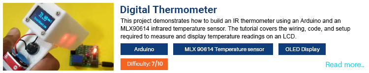
In our daily lives, we use thermometers on various occasions and for various purposes, from medical needs to repair and diagnostic purposes. As you know there are different types of thermometers, and one main classification would be based on how they operate. Some would need to be in contact with the subject to read the temperature. The main issue with these types is that if the contact is it proper the readings would also be inaccurate. Not only that these types of devices are impractical to use during pandemics like COVID. That's where the contactless thermometers come in handy. They offer good accuracy without any of the drawbacks of other types of thermometers. These types of thermometers use infrared sensors to measure infrared radiation from a hot body to accurately calculate the temperature. So, in this project, we will explain how we can make such a non-contact infrared thermometer using an MLX90614 sensor And an Arduino.

2. Automatic Irrigation System

Automatic Irrigation System

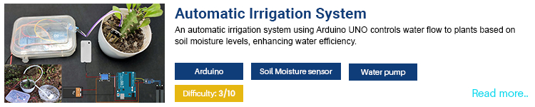
We all like a bit of greenery around, whether it's indoor plants or a garden. They always help us to keep us calm and relaxed. Even though they are low maintenance compared to pets, they need periodic care to keep them alive and fresh. The main concern for plants is soil moisture. It should be at a specific level to keep the plants healthy. Both over watering as well as not watering enough can affect the plant's health. In such situations, we use automatic watering systems to keep the soil moisture at a required level. But the problem is that the commercial solutions are expensive and are not that affordable. That’s why, in this project, we are going to make an automatic irrigation system using an Arduino and a few other cheap and easy-to-find components. We will use a soil moisture sensor to detect the moisture level and then activate a water pump as needed to keep the mixture at the desired level. 

3. Voice Controlled Home Automation 

Voice Controlled Home Automation

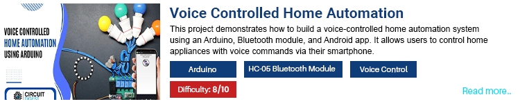
We all know how convenient is to use home automation and voice assistant systems such as Google Home, Apple HomeKit or Amazon Echo. They all offer a convenient and easy way to control our devices using smart devices or voice. But the problem is that they are not that cheap and moreover there can be privacy concerns regarding the data they collect. So, to address these problems we will make an inexpensive voice-controlled home automation system using easy to find components such as Arduino Nano, HC-05 Bluetooth module and relay driver board. The project utilizes an Android App that will convert our voice commands to text and then send it to the Arduino using Bluetooth. Depending on the command received the Arduino will control the connected appliances.  

4. Obstacle Avoiding Robot

Obstacle Avoiding Robot

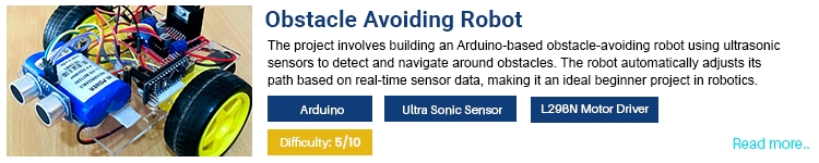
There are plenty of autonomous devices we come across in our daily lives, from autonomous vacuum cleaners to self-driving cars. One major feature of all these kinds of devices is that they are capable of detecting obstacles and objects around them and acting accordingly to avoid crashes or accidents. In this project, we will build such an obstacle-avoiding robot to learn the basics of how they work and how to improve them. Even though there are multiple methods to detect obstacles, we would be using an ultrasonic sensor-based approach they are cheap and easy to work with. In addition to the wheel driving DC motor, we are also using an additional Servo motor to change the ultrasonic sensor direction to make it easier to calculate the optimal driving manoeuvre.

5. Human Following Robot

Human Following Robot

We have seen many types of autonomous robots including obstacle avoiding robots and line following robots. With this project we are going with a different approach and will build a human following robot. The basic working principle behind it is very simple and somewhat similar to an obstacle avoiding robot. But instead of changing direction when an object is detected, this robot will detect the movements and will follow the object. For detecting the object and movement we will use ultrasonic sensors. Unlike traditional designs, which use a single sensor and a servo motor to move the sensor around, we will use multiple sensors. These multiple sensors will be oriented at different angles. Using this method not only we can avoid the use of any moving parts for the sensor, but also the processing would be much faster since all of the sensors can be accessed at all times.   

6. Line Following Robot

Line Following Robot

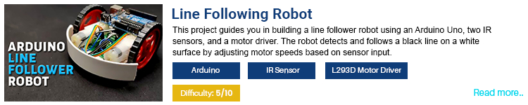
The line follower robot is a very interesting, easy to make autonomous robot. As the name suggests the line follower robot will follow the line drawn on any surface. To build this project we will use an Arduino UNO with a pair of IR sensors and a motor driver. The IR sensors will be placed in front of the robot on each side. The IR sensor contains an IR LED and an IR diode. The IR LED is illuminated always. The infrared light from the LED will be bounced back from any object that will reach the IR diode. Depending on the color of the object or surface the amount of infrared light reflected will be different. This difference is then used to identify the color of the surface. Using this we will determine if the robot crosses or moves away from the line. Since we are using two sensors, we can compare the reading from both sensors to determine to which direction the robot should be steered. Using this algorithm the robot will follow the line. 

7. RFID Door Lock

RFID Door Lock

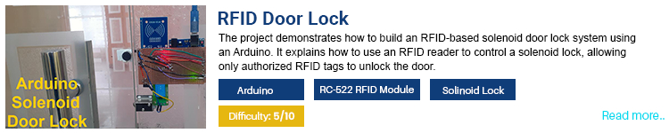
RFID tags are everywhere. From product labels to secure access cards. We have been using them for asset tracking, pet tracking, door locks for hotels and offices and many other applications. The advantages of an RFID system include the tags or cards don’t need any internal power source, they are fast, convenient and mostly secure. Why do we need to use a traditional key, which would take a fair amount of time and effort to lock and unlock, when the RFID door lock can do that within a fraction of a second by just placing the card near it? So, in this project, we will create such an RFID door lock using an Arduino UNO, an RC-522 RFID reader and a solenoid lock. A hall effect sensor is also used to detect whether the door is locked or not.   

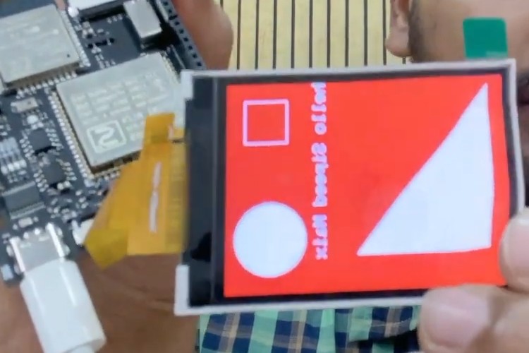
8. Smart Blind Stick

Smart Blind Stick

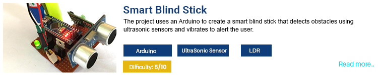
As we know it is hard for visually impaired people to navigate. They have to rely on their hearing and touch to navigate. But even with that, it would be harder to do so, especially in a busy street and other such places. We can help them overcome this difficulty using technology. For that, we will create a smart blind stick. This Smart stick will have an Ultrasonic sensor to sense distance from any obstacle, LDR to sense lighting conditions and an RF remote using which the blind man could remotely locate his stick. All the feedback will be given to the blind man in an audible form through a Buzzer. The buzzer can also be replaced with a vibration motor to get the haptic feedback. 

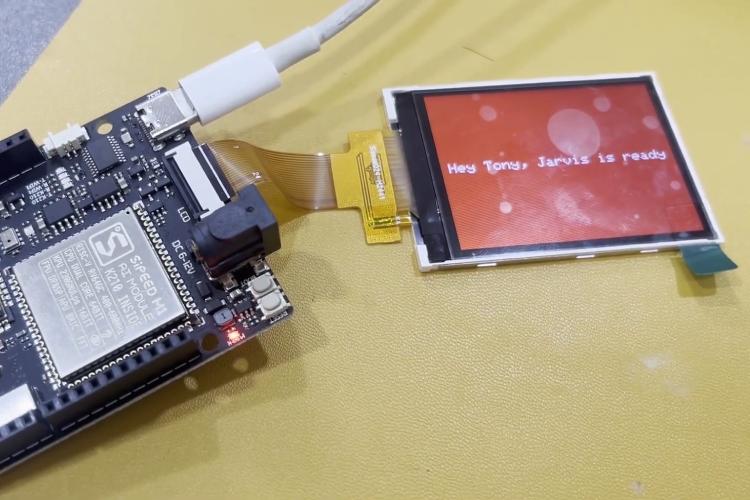
9. Automatic Roller Blinds

Automatic Roller Blinds

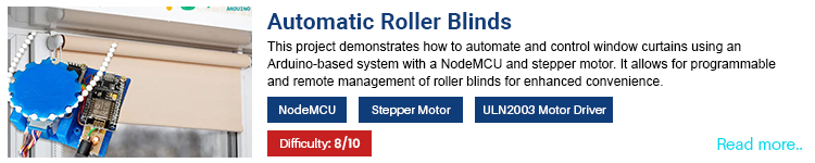
Nowadays most of our household devices are smart devices. how about automating our devices, so that they will operate automatically at a predefined time? You might remember the opening scene of the ironman Movie where the JARVIS AI opens up the curtains and greets Tony Stark. So, in this project, we are going to build an automated motorized blind controller. The main benefit is that this can be used with our existing roller blinds, and we don’t need to buy any special blinds for this project. To get started we have designed a few 3D printed parts, which include a window blind gear and a motor mount. The brain of this project is a NodeMCU development board. A tiny stepper motor is controlled using the NdeMCU at a certain interval to open and close the blinds. One other intriguing feature is that it can also be controlled using voice commands using IFTTT. 

10. Bluetooth Car

Bluetooth Car

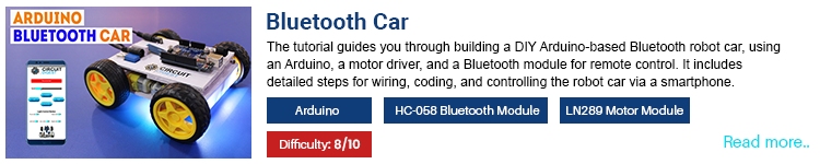
When we were kids, most of us would have been intrigued by remote-controlled toys. Even if we didn’t understand how they worked we were always eager to know the secret and make our own version of that. In this project, we will make such a remote-controlled toy:  a Bluetooth controlled car to be exact. The project is fairly simple to make, and all the components are cheap and easy to find. The brain of the project is an Arduino UNO development board and for Bluetooth connectivity, we have used the HC-05 Bluetooth module. Four BO motors were used to drive the tyres and an L298N DC motor driver was used to control the motors. In addition to that we have also added a few programmable RGB LEDs to the circuit to make it a bit more visually appealing. The chassis and the body of the car are made from perf boards. The car can be fully controlled using a mobile app. Through the app, we can control the movement, speed and all the lights on the car.

11. Smart Prepaid Energy Meter

Smart Prepaid Energy Meter

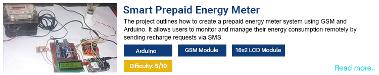
Have you ever thought about using electricity to recharge, just like our mobile phone? You might wonder why we need such a system when we already have a billing system. The main issue with the current billing system is that we don’t have any control over it. We don’t know if we are overusing it. But with this smart prepaid energy meter, we will have full control we will know when we are over a certain usage limit, and by knowing this we can monitor and control our energy usage as per our budget. One other advantage of this project is that we are using an exciting energy meter and interfacing it with an Arduino. By doing this we can ensure that the readings are accurate since the existing commercial meter is calibrated and certified but authorised agencies. The Arduino board interfaced with the analog energy meter using the calibration LED on the meter. The Arduino will count the calibration LED pulses to calculate the energy usage. A GSM module is also integrated with the Arduino to make remote recharge possible. Recharge can be done by sending an SMS. An LCD display is also provided to display the energy usage and remaining balance information. 

12. Heartrate Monitor

Heartrate Monitor

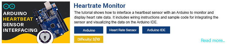
In This heartbeat monitor project, we will learn how to interface a heartbeat sensor with an Arduino board. The construction of the heartbeat sensor is fairly simple. The module contains an LED, an APDS9008 photodetector sensor, an opamp and a few complimentary components. When the LED is illuminated the light penetrates the skin and the blood vessels. The photodetector measures the amount of light that is absorbed or reflected back. As the blood vessels expand and contract with each heartbeat, the amount of light absorbed or reflected changes, allowing the sensor to calculate the heart rate. Using an Arduino, we will read this value and then display it in an OLED display. 

13. Smart Dustbin

Smart Dustbin

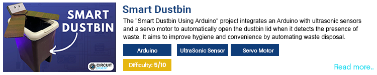
Properly classification and disposal of waste is a very important step in saving the environment. But one problem with using dustbins, especially the public ones is that people are always hesitant to open them because of are afraid that they might be contaminated or because disgusted to do so. Because of this people may even through the waste around without properly disposing it in a dustbin. To solve this issue, we have created our innovative smart dustbin. The smart dust bin is created using an Arduino Uno development board, an ultrasonic sensor and two servo motors. Whenever the ultrasonic sensor detects a movement within a certain set distance the Arduino will drive the servo motors, and the servo motors will open the dustbin cover that is directly attached to them. Once the waste is disposed into the dustbin and there is no movement the Arduino will then close the dustbin cover after a certain time. By using this smart dustbin, we don’t need to get our hands dirty every time we need to dispose of something into it. 

14. Digital Dice using Arduino

Digital Dice

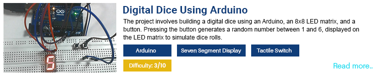
We all are familiar with classic board games such as the LUDO or the Snak and Ladder. We enjoyed playing them while we were kids. One thing common with these games is that we use dice to get a random value to play the games. One problem with traditional dice is that some may get paranoid that the other players can manipulate the dice by controlling how it is thrown. To avoid this, we use countermeasures such as a cup to shake the dice instead of using the hands. So, to avoid this why don’t we create something that can't be physically influenced? For that, we can create a digital dice, which will return a random number and display it on a seven-segment display. To build such a digital dice all we need is an Arduino development board, a seven-segment display, a pair of tactile switches and a few other passive components. When the button is pressed the Arduino will generate a random number and will display it on the seven segments. 

15. Fingerprint Attendance System

Biometric Attendance System

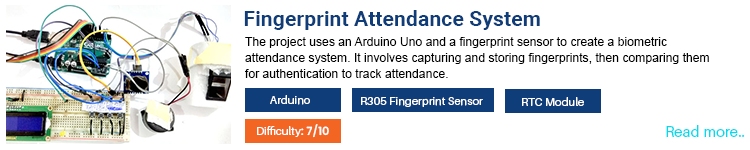
Attendance is very important in offices and educational institutions. There are many ways to mark attendance, from manual roll calling to advanced biometric or RFID-based systems. With this project, we will make a simple and easy to make attendance system using Arduino and a fingerprint sensor. For this, we are using an R305 fingerprint sensor. The R305 is an optical fingerprint sensor with the capability to store up to 512 fingerprint templates. The fingerprint sensor is interfaced with the Arduino using the UART protocol. The project also includes an LCD display for the user interface and a few tactile switches for user inputs. The project also includes an RTC module for accurate timekeeping. 

16. AC Light Dimmer Using TRIAC

AC Light Dimmer

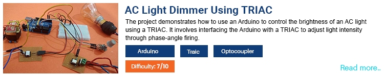
Controlling an AC appliance is very simple, all we need is a relay and some kind of microcontroller, right? It is simple if you only need to turn it on and off. What about a bit more control over them? For example, adjusting the brightness of a bulb or the speed of a fan. For that, we need another technique called phase angle control. So, in this project, we will learn about an AC lamp dimmer using Arduino and TRIAC. Here a TRIAC is used to switch the AC lamp, but you can also use this for any other inductive or resistive loads. We will also learn about zero crossing detection, its importance and how to implement it.

17. Air Quality Monitoring

Air Quality Monitor

Air pollution is a major concern that adversely affects the environment, public health, and overall quality of life. It is a result of harmful substances being released into the atmosphere, including carbon monoxide, sulfur dioxide, nitrogen oxides, and volatile organic compounds. Air pollution around us can lead to respiratory diseases, cardiovascular problems, and other serious health conditions. This air quality monitor project is aimed at providing real-time insights into the air quality around us. This air quality monitor is built around an Arduino UNO featuring an MQ135 air quality sensor, a DHT11 temperature and humidity sensor and an OLED display to display all the information to the user. 

18. Wireless Doorbell Arduino

Wireless Doorbell

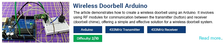
We are all familiar with wired doorbell systems. it is very essential for someone outside our door to call us. Even though they work, they have numerous disadvantages. Major advantages include they need to be installed by professionals to work properly, doorbell switches are normally connected to mains voltage and damages to the switch may result in electrocution and since the switch is normally situated outside humidity and water can also cause electrical leakage. Another issue with it is that it requires more work and time to install a wired doorbell system in an existing home. To overcome these issues, we are going to build a wireless doorbell. Since all of the parts are low-voltage components we can power them using batteries so that there is no risk involving the mains voltage. Not only that since it is wireless we don’t need to do any extensive wiring, and if powered with batteries they can act as a standalone unit without any wires or cables sticking out. 

19. Digital Alarm Clock

Digital Alarm Clock

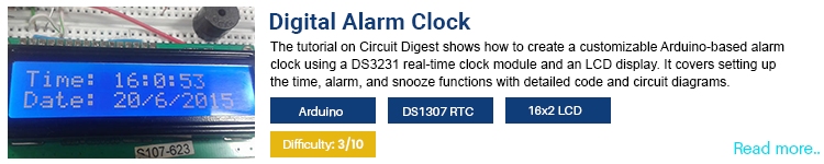
Don’t you get bored by ordinary analog alarm clocks? What about making your own alarm clock? That too with very minimal components. So, let’s build one our own. So, in this project, we are going to build a very simple and easy to make alarm clock. For this project, we are going to use an Arduino Pro mini with an RTC module, a buzzer and some other basic components. The DS1307 RTC chip will keep an accurate time even when the power is disconnected, all we need is to connect a small RTC coin cell to the RTC chip. The time will be displayed on a 16x2 LCD module, and the time and alarm can be set using a few tactile switches connected to the Arduino.  

20. Pet Feeder

Pet Feeder

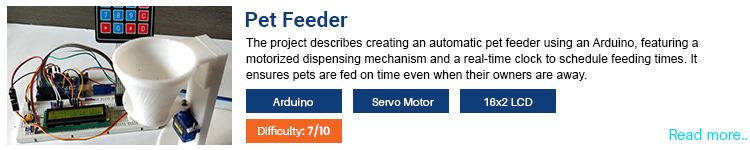
An automatic pet feeder is a modern solution designed to ensure pets receive timely and appropriate portions of food, even in the absence of their owners. Such an automatic pet feeder is particularly beneficial for busy pet owners who may not always be home to feed their pets at regular intervals. But the problem with the commercially available ones is that they are not particularly pocket friendly. So, we are going to build an easy to make, pocket friendly, DIY automatic pet feeder. With this DIY version, we can feed our pets in a set time. Our version of the pet feeder features an Arduino UNO as the brain, a 16x2 LCD for the user interface a matrix keypad for user inputs, an RTC module for timekeeping and a servo motor for controlling the dispensing mechanism. The dispensing mechanism is built using some 3D printed parts and can be integrated very easily. 

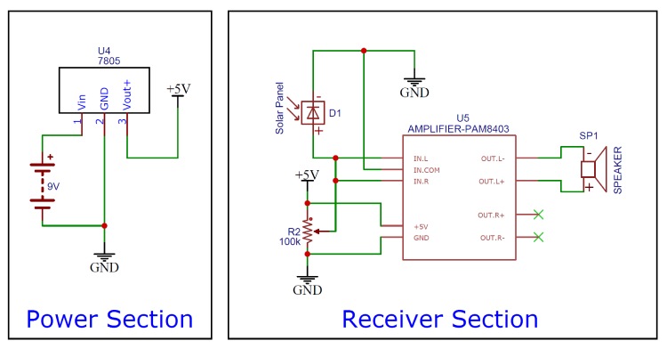
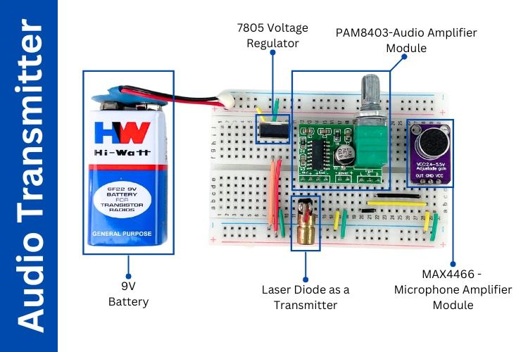
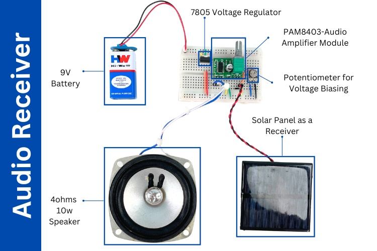
21. Simple Music Player

Music Player

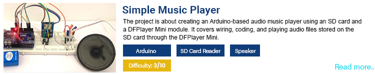
Adding sounds or music to our projects not only makes them look cool and attractive, but they would also come in handy to provide audible feedback to the user. In this project, we will learn how to do so, without the need for any special MP3 or music player modules. We will use a technique called pulse code modulation also known as PCM in short to generate the sound. The sound files will be saved in an SD card as a wave file and the Arduino will read them using an SD card module. The Arduino will output the sound through one of its GPIO and it will be amplified using an LM386 based audio amplifier before feeding to a loudspeaker. A couple of tactile buttons are also included in the circuit for the playback controls. 

22. Sound/Noise Monitoring

Sound Monitor

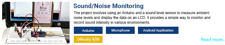
Just like any other type of pollution, sound pollution is also a major concern nowadays. Especially in cities where there is a lot of traffic and machineries that operates non-stop. Now you might wonder how exactly to measure sound pollution. For that, we have specialized equipment called decibel meters. which will give you an accurate reading of the noise or sound around you. So why don’t we make our own sound/ noise monitor to detect the accurate sound levels? For that, we are going to use a microphone attached to a preamplifier built around an LM386 amplifier chip. The output of the amplifier section will then be monitored using an analog pin of an Arduino board. The Arduino will then use this ADC reading to calculate the sound level in dB. The resulting value will then be displayed on a serial monitor for the user. 

23. Whistle Detector Switch

Whistle Switch

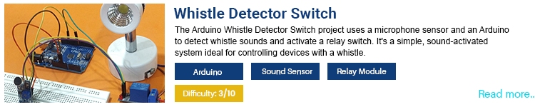
When we were a kid, most of us would have been fascinated with toys that were activated by claps or sounds. Not only just toys but there are even commercial as well as DIY versions of clap switches that can be used to control our lights or appliances with claps. Even though they work miraculously, they have one major disadvantage- they might get triggered by any kind of loud noises, like a loud radio or a neighbour’s lawn mower. So, to overcome this issue we are going to build a whistle detector switch. Unlike other sounds the whistle will have a uniform frequency for a particular duration and hence can be distinguished from speech or music. So we don’t need to worry about the false triggering. For this, we are going to use an Arduino Uno along with a sound sensor module, a relay and some other basic components. The sound sensor module will capture the sound using the onboard microphone and will give an amplified signal at the output. The frequency of this signal will then be calculated using an Arduino development board, and if the frequency matches that of a whistle the Arduino will activate or deactivate the relay resulting in controlling the load.  

24. Automatic Water Dispenser

Automatic Water Dispenser

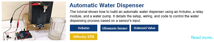
Even though our earth is mostly covered by water the amount of drinking water is very low. But the concerning reality is that this amount of drinking water is getting reduced drastically due to factors such as population explosion, pollution, climate change and water wastage. it is very important to avoid even a drop of water being wasted. It might not appear big at first time, but if your tap dripped a drop of water once every second it would take only about five hours for you to waste one gallon of water, that is enough water for an average human to survive for two days. So as a solution for such unwanted and unrecognised water wastage, we are going to build an automatic water dispenser which can replace the manual taps and reduce water wastage. Not only that as added bonus we can even avoid contamination from using the public taps. An Arduino Uno is used as the brain of this project. An ultrasonic sensor is used to detect the movement and if a movement is detected the Arduino will activate a solenoid valve to dispense a certain amount of water. After dispensing a set amount the valve will be automatically closed and thus avoid any water wastage.   

25. Basic Piano with Record and Replay

Electronic Piano

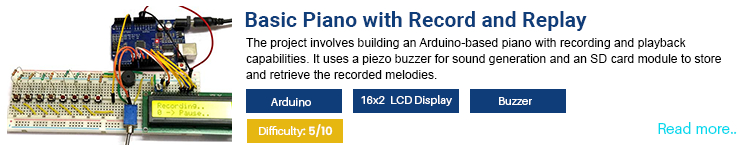
As a child, I was always fascinated by the music keyboard. It was always fascinating to see the musician not only playing new tunes but also combining them with prerecorded tunes. So why don’t we make a DIY version of that? So, in this project, we are going to build an electronic piano with the ability to record and replay the tones. An Arduino uno will handle all the processing and user inputs. An LCD display is provided for the user interface and a couple of buttons for user inputs. Depending on the button pressed the Arduino will save a corresponding tone to the memory. A simple piezoelectric buzzer is used to provide the sound output. For the button inputs, we have used a cleaver technique, that involves a resistor ladder network. by using this method, we were able to interface the whole 8 switches using a single analog pin.   

26. Arduino Inclinometer

Inclinometer

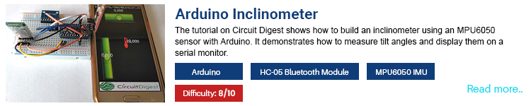
Inclinometers are used for measuring the angle of inclination of something or some surface. A simplified version of such an inclinometer is known as a spirit level. Traditionally, spirit levels have been the go-to tool in construction for ensuring surfaces are level and angles are accurate. However, they are limited to manual readings and lack digital precision. Even though there are digital inclinometers, they are expensive. So, we are going to build a digital inclinometer using Arduino. Our version of the DIY digital inclinometer consists of an Arduino Pro mini, An MPU6050 MPU and an HC-05 Bluetooth module. The Arduino will use the reading from the IMU to calculate the angles and the result will be sent to a smartphone via Bluetooth. Our custom-made Android app will display a virtual level with the readings corresponding to the reading from the Arduino.     

27. Arduino Calculator

Arduino Calculator

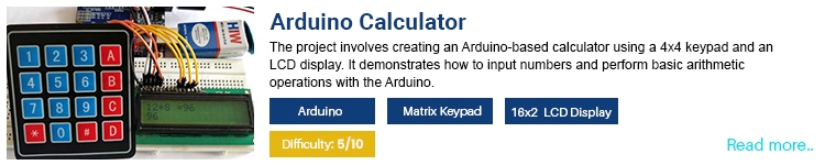
In the market, there are several types of calculators available, from simple arithmetic calculators to more advanced scientific and graphing calculators. In this project, we will learn how to make a simple calculator using an Arduino development board, an LCD display and a matrix keypad. The used inputs are captured using a 4x4 matrix keypad and the calculation result will be displayed on a 16x2 LCD display. With this project, we will learn how a matrix keypad works and how to interface it with an Arduino. 

28. Automatic AC Temperature Control

AC Temperature Control

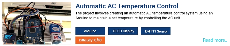
Air conditioners once considered a luxury have now become a necessity to combat the harsh climates. However, those who own an AC often share a common concern: high electricity consumption and the associated costs. This project aims to develop a compact Automatic Temperature Control Circuit designed to reduce electricity bills by automatically adjusting the AC's temperature based on the room's ambient temperature. By periodically varying the set temperature, we can prevent the AC from running at lower temperature settings for extended periods, thereby reducing power consumption and improving user comfort. The automatic AC temperature controller is built around an Arduino mega development board. A DHT11 sensor is used to detect the ambient temperature and humidity. A TSOP1738 IR sensor is used to decode the AC remote signal, and an IR LED is used to transmit the control signals to the AC unit. 

29. Control Computer with Hand Gesture

Gesture Control

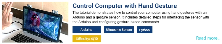
There are multiple ways to control a computer, using a keyboard, mouse or even with specialized remotes. How about hand gestures? Of course, we can use hand gestures. It would be interesting to make a device that can be used to control our computer with simple hand gestures. So, let's build one. For that, we are going to use a very simple setup consisting of only an Arduino UNO and a pair of ultrasonic sensors. We will place two Ultrasonic sensors on top of our monitor and will read the distance between the monitor and our hand using Arduino, based on this value of distance we will perform certain actions. For the PC side, we would utilize Python with pyautogui library. The best use case for such control would be the media control. We can simply control the media playback or volume controls using this setup.   

30. Automatic call Answering Machine

Automatic Call Answering Machine

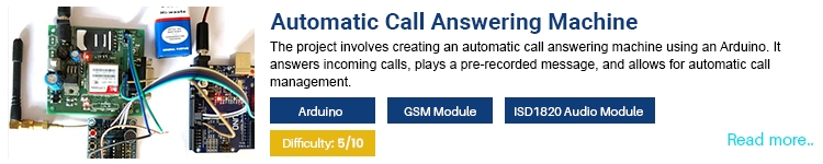
Most of the time when we call a customer support line, we are greeted with an Interactive Voice Response System also known as IVRS in short. Have you ever wondered how these IVRS systems work without any human intervention on the server side? To demonstrate it’s working we are going to build an automatic call answering machine. For the project, we are going to use an Arduino Uno development board as the main controller. A GSM module featuring SIM900 GSM SoC is used for the communication side of the project. The GSM module is interfaced with the Arduino using UART protocol and AT commands are used to control the module. For the audio section, we are using the ISD1820 Voice module. The ISD1820 module is capable of recording an audio clip for 10 seconds and then playing it when required. Whenever a call is received on the GSM module the Arduino will automatically answer the call. Once the call is answered the Arduino will start the audio clip playback. The audio output is connected to the mic input of the GSM module, thus whenever the audio is played the caller will be able to hear it.     

31. Real Time Face Detection and Tracking

Face Tracking

Building a real-time face detection and tracking system is not a simple task; it would require deep knowledge of programming and machine learning. But we can make a simple version of it without needing complex programming frameworks. To demonstrate that we are going to create a face-tracking robotic arm using an Android phone's camera and Arduino-controlled servos. The project uses Bluetooth to wirelessly connect the Arduino Nano to the Android phone, which handles image detection and sends movement commands to the servos. This setup includes SG90 servo motors and a 9V battery, allowing the robot to follow your face and keep it centred on the screen. The Android application, developed using Processing for Android, can be customized or downloaded as an APK file. 

32. Speedometer

Speedometer

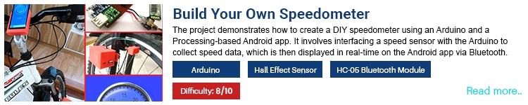
In this DIY Speedometer project, you can create a portable speedometer for bikes or vehicles using Arduino and a Processing Android app. Powered by an 18650 Lithium cell, the device is highly portable and can also charge your mobile phone while displaying speed. Speed measurement is achieved using a Hall sensor and a small magnet attached to the vehicle's wheel, with the Arduino calculating the speed based on the time taken for wheel rotations. The Arduino broadcasts speed data via Bluetooth to an Android phone. Our custom build application will display the received data on the phone using an attractive dial gauge. The application is developed using processing for Android and can be customized or downloaded as an APK file. The project guides you from start to finish, including mounting the kit on your vehicle. 

33. Samart Vacuum Cleaner

Smart Vacuum Cleaner

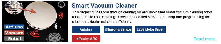
Robot vacuum cleaners have become increasingly popular due to their convenience and efficiency in maintaining clean floors with minimal human intervention. These devices can navigate around furniture, avoid obstacles, and cover large areas systematically, ensuring thorough cleaning. The problem with most commercially available ones is that they are relatively expensive. So building your own Arduino-based Smart Vacuum Cleaner Robot for automatic floor cleaning is an innovative solution for maintaining a clean home without the high cost of commercial products. This DIY vacuum cleaner robot is designed to be compact and practical, featuring ultrasonic sensors and an IR proximity sensor to navigate and clean efficiently. The ultrasonic sensors help the robot avoid obstacles, while the proximity sensor prevents it from falling downstairs. Powered by a 7.4V battery, the robot uses a modified portable vacuum cleaner motor for suction. The housing for the smart vacuum cleaner is built using easily available MDF boards. 

34. Solar Tracker

Solar Tracker

The best way to power our devices without destroying our earth would be to use renewable energy sources such as solar or wind power. But even though they are clean, pollution-free and don't need any fuel, they are highly dependent on some environmental factors. For example, wind turbines depend on wind speed and availability while solar panel depends on the availability of sunlight. To get the best performance from a solar panel all day long, it is necessary to align the solar panel in a way that it will receive the maximum sunlight throughout the day. For this, we would need a solar tracker. So, in this project, we would make an inexpensive but effective solar tracker prototype using an Arduino. two LDRs are used to detect the light intensity. Depending on the reading from the LDR the Arduino will re-align the solar panel using a servo motor.    

35. Water Quality Testing

Water Quality Tester

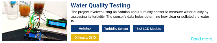
When it comes to water quality, one of the main testing standards is turbidity, which refers to the cloudiness or haziness of water caused by suspended particles, such as silt, clay, microorganisms, and organic and inorganic matter. It is a measure of how much light is scattered by these particles when shined through the water. A turbidity sensor would have two parts, a transmitter and a Receiver. The transmitter consists of a light source typically an LED and a driver circuit. In the receiver end, there is a light detector like a photodiode or an LDR. When a solution under test is placed in between the transmitter and receiver, the sensor would give an output signal depending on the solution. This project aims to build a turbidity meter based on such a sensor and an Arduino development board. The sensor is interfaced with the Arduino using an analog pin. The result will be displayed on a 16x2 LCD display. 

36. Portable Weighing Machine

Portable Weighing Machine

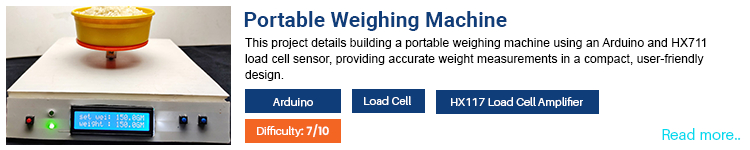
Have you ever wondered how exactly a digital weighing machine works? How do they give very precise weight readings? The modern digital weighing scales use a sensor called load cells. A load cell works by converting a mechanical force into an electrical signal using strain gauges. When force is applied to the load cell, it deforms slightly, causing a change in the electrical resistance of the strain gauges, which is then measured and converted into a corresponding electrical signal proportional to the force. this signal is then used to calculate the actual weight. To understand the actual working of a digital weighing machine, we are going to build a DIY portable weighing machine using an Arduino UNO board and a load cell with a load cell amplifier. The load cell amplifier module consists of HX711 IC, which is an amplifier chip specifically designed for this application. A 16x2 display is used for displaying the weight information to the user.      

37. Wireless RC Boat

Wireless RC Controlled Boat

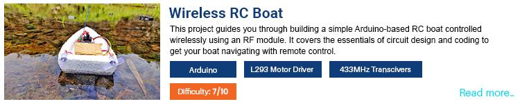
In this project, we will build a remote-controlled Arduino Airboat that can be controlled wirelessly using radio frequency. In the transmitter section, An Arduino Pro mini is used as the main controller. And for communication, we have used a 433MHz transmitter, that uses Amplitude Shift Keying (ASK) protocol. Tactile switches are used for user inputs. In between the Arduino and the transmitter an encoder chip is used. On the receiver side, the 433MHz receiver is connected to a decoder chip and the output of the decoder is then used to drive the motor driver. The entire body of the board is built using thermocol because it is lightweight and easy to handle with. Propellers are made using plastic sheets. The propellers are then attached firmly to the motor shafts and the motors themselves self are then attached to the boat’s body. 

Have any question realated to this Article?

Ask Our Community Members

How The Union Budget 2024-25 Will Make India Self-reliant in Electronics and Semiconductor Manufacturing

Around Rs 21,936.90 crore has been provided to the MeitY for its expenditure, which is a 52 percent boost counting the last year's budget.

Post Lok Sabha elections, Finance Minister Nirmala Sitharaman presented her seventh union budget 2024-25, which is committed to the four pillars of the development agenda: ‘Garib’ (Poor), ‘Mahilayen’ (Women), ‘Yuva’ (Youth) and ‘Annadata’ (Farmer). The current budget placed greater importance on boosting self-sufficiency, or Aatmanirbharta  via strategic initiatives with a key focus on developing India’s electronics and semiconductor manufacturing ecosystem and taking India’s digital ecosystem to a greater height. The core focus of the budget is PM Modi’s packaged incentives and initiatives that are designed to craft immense opportunities for 4 crore youths in the coming five years. With a disbursement of Rs 2 lakh crore, the budget will focus on employment generation, skilling requirements, and education.

For the past several years, the government has been undertaking various initiatives to grow the nation’s electronics and semiconductor industry. Various schemes and policies have been unleashed to help the country to move ahead in the global value chain. This year at the budget session, the finance minister has announced a total of Rs 6,903 crore for the semiconductor ecosystem. An additional outlay isn’t announced because in the last year’s budget, a sum of Rs 3,000 crore has been allocated that was later revised to Rs 1500 crore. Around Rs21,936.90 crore has been provided to the Ministry of Electronics and Information Technology (MeitY) for its expenditure. Last year, the budget allocated to the ministry was around Rs 14,421.25 crore. Counting both the outlay, the MeitY received around 52 percent boost in this year's budget. 

In an effort to bolster the ESDM sector in the nation, the scheme for promotion of the manufacturing of electronic components and semiconductors (SPECS) was unleashed in 2020. The scheme offers an incentive of 25 percent on total expenditure for specific electronic items. Under this scheme, an investment of Rs 12,638 crore and committed incentives of Rs1,758 crore have been approved by the government until March 2024.

Industry bodies such as Electronics Industries Association of India (ELCINA) acknowledge the positive steps announced in the Union Budget 2024-25 presented by Union Finance Minister Nirmala Sitharaman, which includes essential measures impacting the electronics sector. The budget introduces significant changes in Customs Duties and extends exemptions that will support value-added manufacturing within the industry.

The budget document further revealed that the government has decided to provide Rs 4203 crore for a couple of ventures for setting up assembly units, discrete and compound semiconductor manufacturing. Counting the total expense allocation proposed in the two year’s budget, Rs 1,500 crore is offered for electronic chip plants in the country, Rs 100 crore for electronic displays and Rs 900 crore for the modernisation of the Semi-Conductor Laboratory in Mohali. In fact, it has also declared to alter the First Schedule to the Customs Tariff Act, 1975, from October 1 in an effort to create new taxation slabs for certain products utilized in Indian semiconductor machines, e-bicycles, and printer cartridges.

What The Industry Leaders Think About the Union Budget 2024-25:

Varun Manwani, Director, Sahasra Group

Varun Manwani, Director, Sahasra Group


Sahasra Semiconductors welcomes the budget and thanks the finance minister for the bold steps taken for supporting the Semiconductor industry. The reduction is BCD on gold to 6 percent is very welcome! Also, the reduction in other key raw materials and inputs that go into the Semiconductor industry will boost further investments. The support provided for education, new skilling and up-skilling will help in job creation and reduce the burden on industries as well as empower people.

Ashok Mehta, Founder and Chairman, Suchi Semicon

Ashok Mehta, Founder and Chairman, Suchi Semicon


The union budget 2024 is industry friendly the finance minister declared rs 6900 crore to support the semiconductor industry our Prime Minister Mr. Narendra Modi is having very good vision for industrial growth and how to protect local industries also govt already give duty free import for capital goods related to semiconductor industries this budget is giving big boost to industry we all are very much happy with this budget.

A. Gururaj, Managing Director, Optiemus Electronics Ltd

A. Gururaj, Managing Director, Optiemus Electronics Ltd


We welcome the initiatives announced in the Union Budget. The significant emphasis on manufacturing is heartwarming and much needed for the growth of the economy. With the substantial expansion of the electronics manufacturing industry, the demand for a skilled workforce has become paramount. The announcement of various skilling initiatives and the scheme to incentivize additional employment in the manufacturing sector, particularly for first-time employees, will provide essential support to industries reliant on skilled workforce, especially in electronics. Furthermore, the proposal to reduce the Basic Customs Duty on mobile phones, mobile PCBA, and mobile chargers to 15% is a positive step. The measures laid out to support the MSME industries are particularly welcome to create a much-needed supplier base for electronics within India. These measures collectively send out a strong message on the manufacturing sector and related ecosystem in India.

Rajoo Goel, Secretary General, ELCINA

Rajoo Goel, Secretary General, ELCINA


I express my appreciation on behalf of the industry for the Union Budget 2024-25, noting its positive changes for the electronics sector. We believe the above measures support and continue the initiatives taken in the last few years to promote value added manufacturing. However, ELCINA and the industry at large are awaiting the announcement of a robust Scheme for promotion of electronic components, parts and modules manufacturing. A detailed representation for the same with analysis of the segment-wise current demand and supply scenario has been presented to MeitY. We urge the Government to take an urgent decision and provide much needed support to this value-added manufacturing segment of the ESDM industry.

Pankaj Mohindroo, Chairman, ICEA

Pankaj Mohindroo, Chairman, ICEA


The concessions are provided to the extent of nil from existing BCD slabs of 10 to 2.5 per cent, depending on the different critical metals. We also welcome the rationalization of tariffs on Silicon Quartz and silicon Dioxide from 5/7.5 per cent to 2.5 per cent. This is a crucial step to propel the establishment of a strong silicon and power semiconductor wafer production ecosystem in the country.

Ashok Chandak, President, IESA

Ashok Chandak, President, IESA


IESA welcomes the budget's strong focus on manufacturing, job creation, MSME support, women's employment and rationalization of customs duty. The initiatives mentioned are expected to act as catalysts for creating a new workforce in the thriving semiconductor and electronics sector which is facing an acute shortage of relevant skills. The Union Budget 2024 appears promising for the government's commitment to making India a global powerhouse for electronics production. 

Key Budget Announcements:

1.    Reduction in Customs Duties:

  • Cellular Mobile Phones and Accessories: The Basic Customs Duty (BCD) on cellular mobile phones, chargers/adapters, and Printed Circuit Board Assemblies (PCBAs) has been reduced from 20% to 15%.
  • Oxygen Free Copper (OFC): The BCD on OFC strips used in resistor manufacturing has been reduced to Nil, subject to Import of Goods at Concessional Rate of Duty (IGCR) conditions.
  • Telecom Equipment: The BCD on PCBAs for specified telecom equipment has been increased from 10% to 15%.
  • Raw Materials: The exemption entries for input items/raw materials for manufacturing connectors have been expanded to include additional items.


2.    Extended Exemptions:

  • Notifications providing exemptions on import duties for inputs and capital goods have been extended from one year to five years, aligning with ELCINA’s recommendations.

There is a slump in basic customs duty (BCD) from 20 percent to 15 percent on certain electronic products such as mobile phones, mobile printed circuit board assembly (PCBA), and mobile chargers.  While announcing the incentives and the tariff lines, the Finance Minister Sitharaman told the parliament, “With a three-fold increase in domestic production and almost a 100- fold jump in exports of mobile phones in the last six years, the Indian mobile industry has matured. In the interest of consumers, I now propose to reduce the basic customs duty (BCD) on mobile phone, mobile PCBA, and mobile chargers to 15 percent.

Muralikrishnan B, President of Xiaomi India told the media, "At Xiaomi India, we have been manufacturing nearly 100% of our smartphones locally with a strong emphasis on sourcing components like PCBA, charging cables, camera modules, and mechanics, among others. The budget announcement will help further strengthen the domestic electronics manufacturing ecosystem. The proposal for a comprehensive review of the tariff rate structure is another positive step that will further strengthen the industry."

Electric Vehicle

In the current union budget, there was no specific announcement for EVs or FAME 3. Prior to the budget, in March 2024, the Electric Mobility Promotion Scheme (EMPS) was announced with an outlay of Rs 500 crore for a period of four months. The EMPS targeted to boost the growth of the two and three-wheeler segment. An additional outlay of Rs 3,500 crore for the PLI Scheme for Automobiles and Auto Components in this year According to Clean Mobility Shift, in 2023-24, the budget estimate was Rs 604 crore while the Revised Estimates turned up to be Rs 483.77 crore. 

Although no outlay has been announced, FM Sitharaman assured to set-up a Critical Mineral Mission for domestic production, recycling of critical minerals, and overseas acquisition of critical mineral assets. Sitharaman added, “Its mandate will include technology development, skilled workforce, extended producer responsibility framework, and a suitable financing mechanism.

Critical minerals like lithium, copper, cobalt and rare earth elements are extremely essential for sectors like nuclear energy, renewable energy, space, defense, telecommunications, and high-tech electronics. “I propose to fully exempt customs duties on 25 critical minerals and reduce BCD on two of them. This will provide a major fillip to the processing and refining of such minerals and help secure their availability for these strategic and important sectors." Sitharaman further added.

How The Budget Proves Promising for The Electronics Industry

Industry body ELCINA appreciates the Government's efforts to address some of the pressing issues faced by the electronics sector. The reductions in customs duties and extension of exemptions are positive steps towards supporting the industry’s growth and competitiveness. However, ELCINA emphasizes the need for a comprehensive scheme dedicated to promoting the manufacturing of electronic components, parts, and modules. Components and key Modules used in electronic equipment have been a major stumbling block for the development of a sustainable ESDM sector in India. The industry bodies believe that till such time that this shortcoming is not addressed, the country will always be dependent on overseas suppliers and will struggle to take a leadership position in the global industry. Urgent measures in this area are required.

Have any question realated to this Article?

Ask Our Community Members

The Roles of Digital Isolators and Optocouplers in Circuit Design

Submitted by Staff on

Once an electrical design engineer moves beyond initial conceptual sketches and delves into the core of the circuit design, incorporating digital isolators and optocouplers quickly becomes integral to the beta design phase of the project.

Digital isolators and optocouplers serve similar purposes in electronics. Both devices provide electrical isolation between two circuits while allowing communication or signal transfer between them. However, they achieve this isolation through different mechanisms, and each device has its own figure of merit (FOM) used to evaluate its performance, efficiency, and suitability for specific applications.

In this week’s New Tech Tuesday, we look at the purpose of digital isolators and optocouplers in circuit design, how they differ, and their optimal applications.

Digital Isolators

Digital isolators are semiconductors that provide electrical isolation between input and output circuits using capacitive, magnetic, or optical isolation techniques. They are primarily used for galvanic isolation—preventing the flow of electrical current between two circuits— or signal isolation—transmitting digital signals across isolated circuits without a direct electrical connection.

Digital isolators transmit signals across isolation barriers using capacitive or magnetic coupling techniques. They typically consist of two digital signal paths separated by insulation, with signal transfer occurring through a modulated carrier signal.

While digital isolators generally consume less power and can achieve higher data transmission rates than optocouplers, they may have more limitations on voltage range.

Optocouplers

Optocouplers, also called optoisolators, use light-emitting and light-sensing components to provide electrical isolation between input and output circuits. They are commonly used for galvanic isolation, noise immunity, or voltage level shifting.

Optocouplers consist of a light-emitting diode (LED) on the input side and a photodetector on the output side. Isolation is achieved by modulating the LED with the input signal, which in turn emits light that is detected by the photodetector, generating an output signal.

Optocouplers are generally more cost-effective compared to digital isolators and are suitable for a wider range of voltage levels. However, they offer slower data transmission rates compared to digital isolators and can degrade over time due to the aging effects of the LED and photodetector components.

The Newest Products for Your Newest Designs

This week’s New Tech Tuesday features galvanic isolation products from Analog Devices and NXP Semiconductors. These products are uniquely suited for applications that require high-speed digital signal transmission or high-voltage isolation.

Analog Devices ADuM320N and ADuM321N dual digital isolators (Figure 1) are high-performance devices that leverage iCoupler® technology to provide robust digital isolation. These dual-channel isolators integrate high-speed CMOS and monolithic transformer technology, allowing data transmission without direct electrical connection. Unlike traditional optocouplers, which use LEDs and photodetectors to transmit data optically, iCoupler technology uses micro-transformers to achieve isolation. They support high data rates up to several megabits per second, ensuring minimal signal delay and jitter.

ADuM320N and ADuM321N Digital Isolators

Figure 1: The ADuM320N and ADuM321N digital isolators offer independent data channels in various configurations. (Source: Analog Devices)

NXP Semiconductors GD3162 Advanced IGBT/SiC gate drivers are designed to drive the latest silicon carbide (SiC) and insulated gate bipolar transistor (IGBT) modules, particularly for electric vehicle (EV) traction inverters. The GD3162 is a single-channel, galvanically isolated gate driver that provides robust isolation between the control and power stages. This isolation is crucial for maintaining signal integrity and protecting low-voltage control circuitry from high-voltage power transients.

Single-Channel Gate Driver

Figure 2: The GD3162 is an advanced, AEC-Q100 grade 1 qualified, single-channel gate driver designed to drive SiC and IGBT modules for EV traction inverters. (Source: NXP Semiconductors)

Tuesday’s Takeaway

Digital isolators and optocouplers perform similar functions in electronics, providing electrical isolation between two circuits while allowing communication or signal transfer between them. However, they achieve this isolation through different mechanisms and have distinct characteristics. Digital isolators provide faster data rates, reduced power consumption, and longer lifespans, but they can be more expensive and have limited voltage ranges. On the other hand, optocouplers provide greater voltage isolation and wider voltage ranges while being cost-effective; yet, they may have slower data rates and are vulnerable to aging effects. Ultimately, the engineer's electrical design requirements and the device’s FOM determine the decision between them.

Original Source:  Mouser

About the Author

 Rudy Ramos  Rudy is a member of the Technical Content Marketing team at Mouser Electronics, bringing 35+ years of expertise in advanced electromechanical systems, robotics, pneumatics, vacuum systems, high voltage, semiconductor manufacturing, military hardware, and project management. As a technology subject matter expert, Rudy supports global marketing efforts through his extensive product knowledge and by creating and editing technical content for Mouser's website. Rudy has authored technical articles appearing in engineering websites and holds a BS in Technical Management and an MBA with a concentration in Project Management. Prior to Mouser, Rudy worked for National Semiconductor and Texas Instruments.

Have any question realated to this Article?

Ask Our Community Members

Wireless Audio Transfer Using LASER Light

In this article, we are going to discuss how to transfer audio through laser light. This is a fun little project and the concept is similar to what we see in fiber optics cable, we will use a laser light to send data from one point to another. To be particular, in this project here we are going to transfer our voice from one point to another by shining a laser light on a solar panel. This is made possible by Light Fidelity or (Li-Fi) in short, for those who are new Li-Fi is a technology in which data can be transferred using light, in our case we sending our voice as data and using Laser as light source. 

Wireless Audio Transfer Using LASER Light Project’s Hardware Image

The highlight of this project is its simplicity, you can easily build this over a weekend with commonly available components. If you are interested in Li-Fi you can also check our our Li-Fi Text communication and Li-Fi audio transfer projects. 

So, without further delay, let’s dive into building the project.

How to transfer Audio using Laser Light?

Transmitting Audio via Laser light is simple than it sounds. On the transmitter side we have a microphone which converts our voice into electrical signals, this signal then amplified using an audio amplifier and the output of this amplifier is directly connected to a LASER diode. This light is then pointed towards the solar panel on our received circuit. Agian, on the receiver side the solar panel is connected as audio input for another audio amplifier which amplifies these signals and plays it on a speaker. All of this works because of the ability of light to carry data.

Transmitter Side

Audio to Electrical Signal:

Our aim is to transfer the live audio signal, so in that case, we need some sort of microphone to convert the audio signal to an electrical signal. Actually, speaking, there comes a little bit of a complex circuit to achieve a perfect output. So, to make it simple, we are going to use the MAX4466 Microphone Amplifier Module, you can check out the link if you want to know more about this microphone module.

Above, you can see the GIF video representing the working of the MAX4466 Microphone Amplifier Module. Now we have the electrical signal that needs to be transmitted over the laser.

Electric Signal to Laser Beam:

In the above process, we have received the electrical signal. Now this electrical signal is used to drive the laser light beam. It can be done using multiple ways, like using some analog circuits (i.e., switching MOSFET). But to make it simple and more effective, we are using a Mini 5V Audio Amplifier Module based on PAM8403, as you can see in the image below.

PAM8403 Audio Amplifier Module

The reason behind choosing this is simple. It works in the 5V range, so it can be easily integrated with the MAX4466 Microphone Amplifier Module. It also has an inbuilt potentiometer to adjust the amplitude of the output, and more importantly, it is more affordable. You can use whatever amplifier board you have or even create your own circuits to do the job right. Still, I suggest using the audio amplifier board for better output and hassle-free work. We have previously used the PAM8403 to also build a simple DIY Bluetooth speaker, you can check that out if you are intrested.

Now, a laser diode can be connected to the output of the PAM8403 module.

 Laser Diode

Above, you can see the laser diode we are using. If you would like to reduce the current fed to the laser, you can use a resistor of minimum value. Here, the laser we are using has a built-in 30-ohm resistor in series with the power input. If you feel like reducing the power, you can do so by adding an extra resistor in series or even adjusting the potentiometer in the PAM8403 module.

Receiver Side

Laser Light to Electrical Signal:

As in the last step we have already completed the transmitter side, here we go with the receiver side. So the primary process is to convert the audio signal from the laser light beam to its original state of electrical signal. Here, generally, we can use any light-based sensor (i.e., LDR, photodiode, etc.) to do the job right, but those with smaller reception areas are quite tough to use. However, they are not unusable; you can even use them. But here in this project, I am going to use a larger array of photodiodes, which is also known as the solar panel.

Mini Solar Panel

I am going to use a small toy solar panel. Despite its minimal power output, it is more than enough for our project. So, by using this solar panel, we are going to convert the laser beam to an electrical signal.

Electrical Signal to Speaker:

The electrical signal from the solar panel cannot be directly fed to the speaker due to its low power output. Even with a larger solar panel, the small point of light hitting the panel doesn't make a significant change in the output; we will only get a higher DC voltage with a larger panel. However, we need an analog voltage.

To solve this issue, I am going to use the same amplifier module that we used on the transmitter side so that the output electrical signal can be effectively amplified and passed to the speaker.

Regarding the speaker, you can use any speaker compatible with your amplifier module. I am using a 4-ohm, 10-watt speaker, as shown in the image above.

Therefore, we have successfully completed the theory part. I hope you all understand the main concept behind choosing the components and the workings of the project. So, let’s move on to the hardware part of the project.

Components Required for Wireless Audio Transfer Using Laser Light Project

Below is the list of required components to build the Wireless Audio Transfer using a laser light project. Some components may have alternates. To learn more about that, read the “Concept of Audio Transfer Via Laser - Explanation” available above.

  1. Solar Panel - x1

  2. Laser Diode - x1

  3. Resistor (30 ohms) - x1

  4. Potentiometer (100k) - x1

  5. Speaker (4 ohms, 10W) - x1

  6. MAX4466 Microphone Amplifier Module - x1

  7. 7805 5V Voltage Regulator - x2

  8. PAM8403 Audio Amplifier Module with Potentiometer - x2

  9. 9V Battery - x2

  10. BreadBoard - x2

  11. Jumper Wires - Required Quantity

Circuit Diagram of Wireless Audio Transfer Project Using Laser Light

Here this project is built by keeping in mind that to make it easy and use only Minimal components. So, as an outcome, the circuit is simple for Everyone to understand and recreate.

Transmitter Part:

Here you can see the Schematic of the transmitter part. Those connections are self-explanatory.

Schematic Diagram of the Transmitter Section

We can split the schematic into two parts: The power and Transmitter Section.

Power Section:

Here, the power source selected is a 9V battery. Since the rest of the circuit operates at 5V, I am using a 7805 5V Linear Voltage Regulator to effectively convert 9V to 5V.

Transmitter Section:

In this section, only four components are being used. 

Both the MAX4466 and PAM8403 modules are powered using the 5V output from the voltage regulator. The output of the MAX4466 Microphone Amplifier Module is connected directly to the PAM8403 Audio Amplifier Module.

The PAM8403 supports 2 channels. You can use one channel alone or use both channels as I have. However, we are going to drive only one laser. The laser's positive and negative terminals are connected in parallel with one of the channels. While connecting, I have mentioned using a 30-ohm resistor in series. This is for limiting the current flowing through the laser diode. If you are using the same laser diode as me, this resistor is not needed as it already has a 30-ohm resistor connected internally.

Receiver Part:

Below you can see the schematic of the receiver part. You might notice a similar power section here like the transmitter part, as our requirement is still the same. We are powering the system using 5V.

Schematic Diagram of the Receiver Section

Receiver Section:

Here, the solar panel’s negative side is grounded, and the positive side is connected to the input of the PAM8403 Audio Amplifier Module. Like the transmitter, I kept both input channels connected. An extra step is applying the bias voltage to the input using a potentiometer, which sets the DC offset to the input of the amplifier. Finally, a speaker is connected to the output of the PAM8403 amplifier module.

That completes our circuit. Next, let us move on to the assembling part.

Building the Circuit

Let's build the circuit according to our schematic. I am using a breadboard to assemble all the components.

Assembled image of Audio Transmitter

Above, you can see the assembled image of the transmitter with its parts marked for your reference. The laser diode is directly soldered to a 2x2 Berg strip connector, allowing it to be easily fixed to the breadboard. Similarly, the battery connector is also fitted with a Berg strip for easy breadboard integration.

In this transmitter, there are two configurable areas. One is the gain adjustment in the MAX4466 Microphone Amplifier Module, which controls the sensitivity of the microphone. The other is the amplitude adjustment in the PAM8403 module, which controls the output power to the laser diode. These configurable options allow for precise signal control.

Assembled image of Audio Receiver

Above, you can see the assembled image of the receiver. Parts like the speaker, solar panel, and battery are connected to the breadboard using Berg male strips, which I have soldered to the wires and fixed to the breadboard.

Like the transmitter, the receiver also has two configurable options. There is a potentiometer connected to the input of the PAM8403 module, which is used to set the DC offset to the input signal. The PAM8403 module itself has a potentiometer to adjust the amplitude of the signal going to the speaker, effectively allowing volume adjustment.

With this, we have completed building the circuit as per the schematic diagram. Next, Working demonstration.

Working Demonstration of the Wireless Audio Transfer Project

After successfully assembling the components, we began testing the project. It works well both indoors and outdoors, regardless of the conditions. The range of the wireless transfer is impressive, as the intensity of the laser does not diminish significantly under clear weather conditions. As long as the laser beam hits the solar panel, the audio is transferred seamlessly. We also tested the setup from multiple angles and encountered no issues.

The image above was taken while testing the setup outdoors. Unlike other projects, I did not include any GIFs to show the working process, but we have made a video that you can watch below. The video provides a complete demonstration and explanation of the project.

Some of the Improvement Ideas & Additional Possibilities for this Wireless Audio Transfer Project

These are some of my ideas for extending this project, which you can give a try.

Improvement ideas:

  1. Use a more sensitive photodetector instead of a toy solar panel, such as an avalanche photodiode (APD), to improve the reception quality and range.

  2. Implement a focusing lens system to concentrate the laser light on a smaller, more sensitive area of the photodetector.

  3. Introduce noise reduction techniques and filters to improve the audio signal quality.

  4. Some sort of Automatic Alignment System to ensure optimal signal transmission even with movement or misalignment.

Additional Possibilities:

  1. Expand the project to support bidirectional communication by incorporating a similar setup on both ends, allowing two-way audio transmission.

  2. Adapt the system to transmit not only audio but also other types of data, such as digital signals for internet communication, by incorporating appropriate modulation techniques.

  3. Experiment with different laser wavelengths and power levels to extend the effective range of communication, ensuring long-distance transmission capabilities.

  4. Design a compact, battery-operated version of the system for portability, making it suitable for mobile and field applications.

Frequently Asked Questions

1) Can we use laser in Li-Fi?

Of course, you can use lasers in a Li-Fi system. Practically, any light source along with its sensor can be utilized to create a Li-Fi system.

2) Is LiFi Better than Wi-Fi?

Determining whether Li-Fi is better than Wi-Fi depends on various factors. Both have their own pros and cons. For a detailed explanation, visit our article LiFi vs WiFi.

3) Is LiFi Safe for Humans?

Yes, LiFi (Light Fidelity) is generally considered safe for humans due to its Non-Ionizing Radiation, Low Power Levels, Limited Range, etc. Overall, LiFi is a promising and safe technology for wireless communication, offering a secure and efficient alternative to traditional radio frequency-based systems.

4) Advantages and Disadvantages of LiFi?

Advantages of Li-Fi

High-Speed Data Transfer: Li-Fi provides exceptionally fast data transfer rates, often surpassing those of traditional Wi-Fi, by utilizing visible light.
Enhanced Security: Since light cannot pass through walls, Li-Fi offers better security against unauthorized access compared to radio frequency systems.
No Radio Frequency Interference: Li-Fi avoids issues related to radio frequency interference, making it suitable for environments sensitive to such interference.
Reduced Latency: Li-Fi can achieve lower latency compared to Wi-Fi, benefiting applications requiring real-time communication and streaming.
Energy Efficiency: Li-Fi can make use of existing LED lighting systems, which are energy-efficient and help lower overall energy consumption.

Disadvantages of Li-Fi

Line-of-Sight Requirement: Li-Fi needs a direct line of sight between the transmitter and receiver, which can limit its range and flexibility.
Limited Range: The operational range of Li-Fi is shorter than that of Wi-Fi due to its reliance on visible light.
Indoor Use Only: Li-Fi is mainly effective in indoor settings where light can be easily managed and controlled.
Light Obstruction: Any blockage or interruption in the light path can disrupt the communication, impacting reliability.
Cost and Infrastructure: Implementing Li-Fi may require higher initial costs and changes to existing infrastructure, such as upgrading to suitable lighting systems.

5) What is LiFi Used For?

Li-Fi (Light Fidelity) provides high-speed wireless communication by using visible light, ultraviolet, and infrared radiation for data transmission. It is employed in various settings, such as secure environments where radio frequency (RF) signals are restricted, including military and healthcare facilities. Li-Fi offers fast internet access and can be integrated with LED lighting systems to deliver both illumination and data transfer. It is advantageous in areas with high RF interference and is used to enhance applications like augmented reality (AR) and virtual reality (VR) with its superior bandwidth and low latency.

6) What is SLD Laser LiFi?

SLD (Surface Light Emitting Diode) laser Li-Fi refers to a technology that utilizes surface-emitting laser diodes to facilitate communication via light. Unlike traditional LEDs that emit light from a single point, SLDs distribute light over a larger surface area, which enhances the efficiency and performance of Li-Fi systems. In SLD laser Li-Fi setups, these laser diodes enable high-speed, high-bandwidth communication using visible light, offering faster data transfer rates compared to conventional LED-based systems. This technology is beneficial for applications demanding rapid data transmission and reliable performance, such as in urban environments and industrial contexts.

Projects in Similar Relm

1) Li-Fi-based Text Communication between Two Arduino

Demonstration of Li-Fi communication using two Arduino boards: text data is transmitted from an LED and a 4x4 keypad and decoded on the receiver side using an LDR. This showcases Li-Fi's ability to facilitate high-speed, optical data transfer.

2) Audio Transfer using Li-Fi Technology

In this project, we’ll build a circuit to transfer audio data using Li-Fi technology.

Have any question realated to this Article?

Ask Our Community Members

QR Code Scanner API for Low-Power Embedded SoC Boards

Over the past years we at CircuitDigest have built a ton of electronics projects and tutorials to help our community to learn and build electronics with ease. Recently we have noticed a huge interest from readers on our ESP32-CAM Projects, especially the ones involving image recognition and object detection. Since the board is capable of taking images and streaming videos we wanted to build more with it, apart from the standard ESP32 video streaming and ESP32cam face recognition.  

Unfortunately, though this low-cost 8$ development board could only get you so far. We were not able to perform any image processing on-board, the Dev. Board even with its external 4M PSRAM is not powerful enough (read easy enough) to build anything useful with it. Our Solution!?

CircuitDigest Cloud - our very own cloud API which you and people like you can use for free to build and test their projects

QR Code Scanner API

This article is about the QR Code scanner API that can be used easily with ESP32-CAM and other low power SoC devices to decode QR code images easily. The API can handle poor quality images and also work with multiple QR codes in a single image. All the heavy lifting with image processing and QR code decoding is handled by the qreader python library on the server side, but you as a user need not worry about that.

Disclaimer: At the time of writing this article our cloud platform is functional but yet to have some cosmetic updates. We intend to build it with time and add more functionalities

Authentication and Authorization:

The QR Code Scanner API is built and maintained by CircuitDigest and is open for everyone to use in their projects. The API key can be created using the “Create Key” button on CircuitDigest Cloud platform. 

CircuitDigest Cloud Platform

This API key has to be sent from your SoC (like ESP-32) to be able to use our APIs. Please also note that all API keys will expire in 24 hours. You can also create a new key every 24 hours to keep your project running. This limit is temporary and is imposed to not overload our server from a single user. We will update this limit based on number of calls in future. 

API Details

The API can be easily used with Arduino code snippets to capture a QR code image and send it to server API for processing. The API scans the QR code and returns a response in JSON format. 

Server Name: www.circuitdigest.cloud
Server Path: /readqrcode
Server Port: 443
Method: POST
Authorization: Authorization: apikey (replace apikey with actual API key)
Content-Type: multipart/form-data; boundary=CircuitDigest
Request Body: The captured image data sent as JPEG file. Filename of image should be same as API key
Response: The server API should return a JSON response containing the decoded information from the QR code.

Note: Sample Arduino code for ESP32-CAM and other development boards can be found at the bottom of this page. 

Response

A sample response code from the API is shown below. Left side shows the image taken from ESP32-CAM and right side shows the response from API call.

QR Scan Response

The decoded QR code can be found at QR_code, in this case “Hello World!”. If the image has more than one QR code all the available results can be found as a list as shown below

Response Image of QR Scanner

The API call also provides the height and width of the image and also the location at which the image is saved. This will help you to check what was captured and sent in your API call. For the above example the captured image is available at www.circuitdigest.cloud/static/c17e3a5831c4eaf8.jpeg which can open on any web browser like shown below 

QR Image

Code Examples:

The API is tested with ESP32-CAM, but it can be used with any Dev boards capable of taking an image and sending to web server. We will link all the tutorials built using this this API below with complete code and circuit diagram like always. 

Create and Share:

Hope this will be useful to quickly test and deploy your ideas. If you have built something using the API do share it with us and we will mention your work on this page. Happy building!! 

Have any question realated to this Article?

Ask Our Community Members

Getting Started with Sipeed Maixduino Development Kit

Nowadays there are a lot of IoT development boards available. But if you look at the AI IoT development board the options are very limited. Even within them, the ones with good performance tend to be expensive, and the ones that are cheap don’t provide enough performance or are limited in some other way. Just like you, we have also been looking for an AI IoT board, that is not that expensive and comes with good performance. That was when we came across the Sipeed MaixDuino Ai Development kit. It is not only reasonably priced but also comes with a lot of useful features and peripherals. That's why we chose this as one of three boards for our upcoming IoT & Edge AI Project Challenge where you can win prizes up to Rs.7,00,000. Not only that you can even win development board and other exciting gooding by just submitting your project ideas. So don’t forget to check out the IoT & Edge AI Project Challenge for more details.

Powered by the Sipeed M1 AI module the Maixduino also comes with exciting features such as an ESP32 co-processor for WiFi and Bluetooth connectivity, a 2.4” LCD, a VGA image sensor, a microSD card slot and an onboard MEMS microphone. All these are packed into an Arduino Uno sized board which is pin compatible with the Arduino Uno R3.

Let’s Unbox It

Now let’s check out the Maixduino package contents. The development board and all its extra components come in a sturdy plastic box which provides protection from any damages.

Sipeed Maixduino Development Kit Unboxing

Within the box, you will find the Maixduino AI development board itself with the 2.5” LCD display and GC0328 VGA Camera Module.

Sipeed MaixDuino Ai Development Kit Features

As we said earlier the Sipeed MaixDuino Ai Development kit is packed with a lot of features. Here are some of the main features listed.

  • Core    RISC-V Dual Core 64bit, with FPU
  • Frequency    400MHz (Can be overclocked to 600MHz)
  • SRAM    built-in 8MB
  • Image Recognition    QVGA@60fps/VGA@30fps
  • Speech Recognition    Microphone array (8mics)
  • Deep Learning Framework: Supports TensorFlow, Keras, Darknet, Caffe, and other mainstream frameworks
  • Peripherals    FPIOA, UART, GPIO, SPI, I2C, I2S, TIMER
  • Video Processing    
  • Neural Network Processor (KPU)
  • FPU Meets IEEE754-2008 Standard
  • Audio Processor (APU)
  • Fast Fourier Transform Accelerator (FFT)
  • Built-in neural network processor
  • Connector: compatible with Arduino interface, TF card slot, speaker port
  • Wireless: Support 2.4G 802.11.b/g/n and Bluetooth 4.2
  • Audio: MEMS microphone, 3W speaker output
  • DVP Camera Interface: 24P 0.5mm FPC connector, support OV2640, OV5640, OV7740, etc.
  • LCD Interface: 24P 0.5mm FPC connector; support 8bit MCU LCD
  • ESP32 Module: For WiFi and Bluetooth Connectivity
  • Development Environment: support for Arduino IED, MaixPy IDE, OpenMV IDE
  • 2.4” 320x240 SPI TFT Display 
  • GC0328 camera VGA Camera module

Sipeed Maixduino AI Development Board Hardware Overview

As you have familiarised yourself with the features, let’s look at the hardware overview for the Sipeed Maixduino Development Board. The Sipeed Maixduino Development Board has all of its components assembled on the same side. Here are parts marking images introducing each main component.

Sipeed Maixduino Development Board Parts Marking

The main attraction on the Sipeed Maixuino development board is of course the Sipeed M1 AI module. The Sipeed M1 module is based on the K210 RISC-V AI processor from Kendryte. K210 comes with a dual-core processor chip with independent FPU, 64-bit CPU width, 8 MB on-chip SRAM, 400 adjustable clock frequency, and double-precision FPU supporting multiplication, division, and square root operation. It also has AI features such as neural network hardware accelerator KPU, voice processing unit (APU), programmable IO array (FPIOA/IOMUX), and Fast Fourier Transform Accelerator. In AI processing, K210 can perform operations such as convolution, batch normalization, activation, and pooling. At the same time, the pre-processing of voice direction scanning and voice data output can also be performed.

For WiFi and Bluetooth connectivity, the Sipeed Maixduino uses an ESP32-WROOM module. Not only that some of the pins are broken out to the Arduino style header for custom usage.The board can be powered from either the DC connector or the USB type C port. The DC barrel connector can accept an input voltage of 6 -12V DC. There are two tactile switches available onboard, one is for board reset and one is for board boot selection. For programming and debugging the Sipeed Maixduino uses a CH552 USB microcontroller. With the specialised ch55x_dualserial firmware the CH552 can create two virtual UART ports which can be used to program the Sipeed M1 module as well as the ESP32 module. It also can automatically detect ESP32 & K210 bootloader messages, and force it to enter ISP mode without the need for any hardware flow control.

The Sipeed Maixduino also contains an MSM261S4030H0 MEMS microphone for audion capturing, a TM8211 DAC for I2S audio decoding and a 3W PA built around NS4150 for audio out. The PA output can be directly connected to a 3W speaker through the 1.25mm pitch JST connector. The board also has an RGB LED located near the MEMS microphone for use outputs. Other LEDs onboard include the power LED along with RX and TX indication LEDs for both Sipped M1 module and ESP32. It also has an onboard microSD card slot for storage explanation. For interfacing the TFT display the board uses a 24-pin 0.5mm FPC connector. The display comes with the kit is a 2.4” ST7789 TFT display with a resolution of 320x240 pixels, and it uses an 8-bit bus for interfacing with the M1 module. The 24-pin camera FPC interface supports various camera modules including OV2640, OV5640, OV7740 and GC0328.

Sipeed Maixduino AI Development Board Pinout

Maixduino Ai Development Board Pinout

The above pinout image clearly shows the basic as well as alternate function of each pin on the Maixduino development board. As you can see some of the pins are directly connected to the Sipeed M1 module while some of them are connected to the ESP32 module. All of the digital pins are attached to the M1 module, while all of the analog pins are attached to the ESP32 SoC.

Even though the shape and pins are compatible with Arduino UNO R3, the output voltage levels of the GPIOs are different. The  Maixduino only supports 3.3V and 1.8V in its GPIOs, which requires great attention when interfacing with external components, otherwise, the board can be damaged. The reset pin is only 1.8V compatible, be careful when using it. The board also comes with the basic Arduino style pin labelling on the bottom of the PCB.

Maixduino Board Pin Labelling

Using the Sipeed Maixduino with Arduino IDE

In terms of software support also the Maixduino doesn’t disappoint us. The Sippeed Maixduino supports many popular frameworks such as MaixPy IDE, PlatformlO IDE and last but not least our favourite the Arduino IDE. It also supports various real-time operating systems such as Free-RTOS and RT-Thread. So our article will be using the Arduino IDE since it is very popular and easy to use. You can find detailed instructions on how to set up the Maixduino IDE can be found in the official Miaxuino documentation. To start with open up the Arduino IDE and add the following URL to the additional board manager URL section in the Arduino IDE preferences.

http://dl.sipeed.com/MAIX/Maixduino/package_Maixduino_k210_index.json

After closing the Arduino preference window search and install the Miaxuino board package through the board manager.

Sipeed Maixduino with Arduino IDE

Once installed select the Miaduino board from the tools menu and also select the appropriate serial port. When connected the device will show two serial ports, select the first one. In the progamer option select the k-flash programmer. If you don’t select it you won’t be able to program the board. Leave other options as same as the default.

Caution: Now before moving forward. some of the libraries that come with the Maixduino board package are old and can cause some compiler errors. To overcome that please go to the Maixduino GitHub repository and download the library folder. Copy all the libraries, except the Adafruit_GFX library within the library folder to the library folder in the board package installation path. When asked to replace all the files. 

To start with let’s open up an example file. Open the basic display example code under the Sipeed_ST7789. Compile the code and upload it to the board. Now the board will display some basic shapes and text on the TFT display. Ensuring everything is working accordingly.

Maixduino Basic Display Example.

Caution: If you face any errors while uploading such as “a programmer is needed for uploading” make sure you have selected k-flash as the programmer in the tool's menu. If the problem still persists, use the upload using the programmer option from the Sketch menu instead of the upload button. If you face a timeout error while uploading, reset the board while holding down the boot button and try uploading the error. If the board is stuck at FT2232 mode with the warning “recv unknown op 96”, change the baud rate to 1Mbps and try the uploading and when it fails change the baud rate to 1.5Mbps and upload again. If you face any error related to the Arduino_GFX library during compilation make sure to remove any existing versions and install version 1.4.8 of the Arduino_GFX library.

To test the camera, open up the sipeed_gc0328 example you can find on the updated libraries you have downloaded from the GitHub. This example will display the video feed from the camera on the TFT screen.

Maixduino Camera Example

The Maixduino also support many advanced applications such as face recognition, speech recognition and many other AI applications. You can find examples for all of these applications in the GitHub repo we have provided before. Before concluding we can also look at one more example, and for that I have selected a speech recognition example. For this, we are going to use the Maix-SpeechRecognizer library by Andri. Download the voice_model.h file and the main.c  file to a folder. Rename the main.c file into an ino file and open it with the Arduino IDE. Make sure the sketch file and the voice_model.h file is in the same folder.

Once the code is uploaded the code, you can interact with the board using the catchphrases “Hey, Friday” or “Hey, Jarvis”. The board will pick your voice through the onboard MEMS microphone, and it will run a speech recognition algorithm on it. To know more about how to train your own catchphrase and how to use it please watch the video attached below. You will also find more details on the board usage and examples we have discussed earlier in the video.

Have any question realated to this Article?

Ask Our Community Members

Designing Asset Tracking Applications with Pre-certified Sensors

Submitted by Staff on

When transporting perishable goods such as food or pharmaceuticals, maintaining consistent conditions is critical to guaranteeing that products arrive in perfect condition. For pharmaceuticals, going outside of the allowed temperature range may potentially render the product unusable. For food transport, inappropriate conditions may lead to overripening or spoilage, thus creating food waste. In both cases, the value of the goods transported is lost when conditions are not tracked properly.

Sensor devices used in these applications must offer a high degree of confidence in their performance and are generally required to meet standards defined by organizations such as the World Health Organization (WHO), the National Institute of Standards and Technology (NIST), and the International Standards Organization (ISO). In this blog, we consider a way to reduce the time and effort spent on certification by using pre-certified sensors.

Rethinking Sensor Certification for Product Design

Aside from using components with the right accuracy specification and calibration, devices used in asset tracking applications require certification. The most important certifications are NIST traceability and ISO17025.

Historically, certification was a step done on the device level, as an additional step in the manufacturing process. ISO17025 certification can only be given by an accredited institution. This meant that devices had to be sent to an accredited third-party lab for testing after coming off the assembly line, which added a costly and time-consuming extra step to the overall manufacturing process.

Today, a new approach is simplifying the accreditation process. By using pre-certified sensor components, product designers can remove the post-assembly third-party certification step, enabling product shipment straight from the production line to the end customer. This allows product designers to guarantee accuracy levels of the shipped devices while increasing speed to market.

To achieve this, Sensirion has gone through the process of ISO17025 accreditation. This allows for end-to-end monitoring, simplified manufacturing, and efficient recertification. By adding Sensirion’s certified SHT43 sensor to their designs, designers can meet NIST traceability and ISO17025 compliance without requiring additional changes in their manufacturing process (Figure 1).

Third-Party Certification Step

Sensor Specification

The Sensirion SHT43 is a state-of-the-art digital humidity and temperature sensor with an I²C interface, offering typical accuracies of 1.8 percent relative humidity and 0.48°C for temperature. With its small size of 1.5mm × 1.5mm × 0.5mm, wide supply voltage range of 1.08V to 3.6V, and low power consumption, the SHT43 is well suited for asset tracking platforms and data logging applications. Reference drivers are available for development setups based on Arduino or Raspberry Pi, along with drivers for the most common microcontroller platforms.

Accessing Certificates via Cloud Services

To access certifications, Sensirion offers a cloud service called Libellus. This service has a web interface to access certificates manually, but more importantly, offers an application programming interface (API). The API can be used during the production process to verify the certification of the specific sensor built into the product, as well as to provide certificates to the end customer of the respective device (Figure 2). The cloud service can be used to obtain documents in portable document format (PDF) and allows direct access to the raw calibration data in JavaScript Object Notation (JSON). This allows device manufacturers to generate certificate documents with all the necessary information on their own (digital) letterhead, ensuring a consistent brand identity.

Sensirion’s Libellus Cloud Service

Accessing Certificates Via the API

Sensor certificates are linked to a sensor’s serial number. The serial number can be read from the sensor via I²C. With the serial number in hand, it is possible to download the calibration data, both as a PDF document and as raw JSON data. The Sensirion API Guide provides a detailed documentation of the Web API.

As an example, here is the cURL command for downloading a sensor certificate as a PDF file for the SHT43 sensor with 123456 as the serial number:

curl --location --request GET \

'https://libellus.sensirion.com/api/SHT43/sensors/123456/certificate?format=application/pdf' \

--header 'Authorization: Token a2b3c4d5token7m8n9o'

Here is a breakdown of the example:

  • The product name “SHT43” corresponds to the product used.
  • The serial number “123456” is the serial number read via the I²C bus.
  • The “Authorization” header token is used to verify user access and is shared with the user upon account creation. If lost, it can be reset under the account profile on the Libellus web interface.

Note that resetting the token will invalidate the older ones; thus, any scripts and processes getting data from Libellus will need to be updated to use the new token.

If the developer prefers to access the raw calibration data, there is a separate endpoint available called “calibration_info” to get this data in JSON, allowing for easy post-processing.

Further Reading

Explore the entire SHT43 product family to see how these pre-certified sensors streamline the design and manufacturing processes.

To learn more about the certification process, differences between NIST and ISO17025, and topics such as recertification or drift estimation, check out Sensirion's in-depth guide on certified smart tracking applications.

Author

 Johannes Winkelmann Johannes Winkelmann is Sensirion's Director for Developer Experience, overseeing initiatives to support engineers in evaluating, prototyping, and designing solutions with sensors. With a background in Software Engineering and a decade of experience in developing software for embedded systems, wearables & mobile devices, he has spent the last ten years in the field of developer relations, with a secondary focus on building relationships with ecosystem partners.

Have any question realated to this Article?

Ask Our Community Members

Getting Started with the MAX78000 Feather Development Board

When it comes to the development board there are a ton of choices to choose from, such as Arduino boards, ESP32 development boards, STM32  Nucleo and Discovery boards, Teensy Boards, STM8 development boards and many more. However, the problem with most of these boards is that it is hard to find a price-to-performance balance. They are either cheap and lack features and performance or they are packed with features and performance with a hefty price tag. Even if you can find a board with a cheap price tag and better performance it most likely will lack any device support.  With that in mind, I would like to draw your attention to the MAX78000FTHR development board from Analog Devices.

The MAX78000 Feather development board comes with a ton of features, including an ARM Coretex M4 processor with Risc-V coprocessor, Convolutional Neural Network Accelerator, CMOS VGA Image Sensor, Stereo Audio CODEC, Digital Microphone, On-Board DAPLink debugger and many more with price of only 32USD. It is designed for ultra-low-power, artificial intelligence (AI) applications. The MAX78000 feather board is not only packed with features, but it also gets great support from the manufacturer, Analog Devices. You can get almost all possible example codes with detailed explanations for easy learning and development.

So in this article, we will be reviewing the MAX78000 Feather development board, and we will go through its features, uses, and example codes. We have also selected the MAX78000 Feather development board for our IoT & Edge AI Project Challenge as one of three boards you can choose from. Check out the contest page for more information and don’t miss the chance to get a MAX78000 Feather development board and other interesting goodies along with a chance to win prizes up to Rs.7,00,000.

It’s Unboxing Time!

Now let’s unbox the MAX78000 feather board. The MAX78000 feather board comes in a sturdy cardboard box. The box contains the board itself, along with a USB cable, a pinout image, and header pins to be soldered to the board. The board is secured in a reusable ESD bag to protect it from any static electricity during shipment or handling.

MAX78000 Feather Development Board Unboxing

MAX78000 Feather Development Board Features

As we said earlier the the MAX78000 development board is packed with a lot of features. Here are some of the main features listed.

MAX78000 Microcontroller

  • Dual Core: Arm Cortex-M4 Processor with FPU, 100MHz, RISC-V Coprocessor, 60MHz
  • 512KB Flash Memory
  • 128KB SRAM
  • 16KB Cache
  • Convolutional Neural Network Accelerator
  • 12-bit Parallel Camera Interface
  • MAX20303 Wearable PMIC with Fuel Gauge
  • Charge from USB
  • On-board DAPLink Debug and Programming Interface for Arm Cortex-M4 processor with FPU
  • Breadboard Compatible Headers
  • Micro USB Connector
  • Micro SD Card Connector

Integrated Peripherals

  • RGB Indicator LED
  • User Pushbutton
  • CMOS VGA Image Sensor
  • Low-Power Stereo Audio CODEC
  • Digital Microphone
  • SWD Debugger
  • Virtual UART Console
  • 10-Pin Cortex Debug Header for RISC-V Coprocessor

MAX78000 Feather Development Board Hardware Overview

Now let’s look at the hardware overview for the MAX78000. Here are the parts marking for the MAX78000 feather board top side.

MAX78000 Feather Board Parts Marking - Top Side

As you can see the board comes with a lot of peripherals. The Micro USB port is used for powering the board as well as for charging, debugging and programming the feather board. The data pins of the USB are directly connected to the MAX32625, which is used for the DAP-Link interface. There an extra JTAG connector is available for debugging the RISC-V core. The board features a JST battery connector for LiPo batteries. This makes it easier to build portable devices and projects with this board. The power management for the entire board is managed by the MAX20303 power management controller. It also contains a fuel gauge feature, which will be useful to detect the state of charge of the connected battery. If we come to the peripherals, the MAX78000 feather board features 2 RGB LEDs, 5 tactile buttons, and a digital microphone. A VGA camera, and Audion line in and out connectors. Out of four tactile switches, one is used as a power button, one is used for the DAP link, one is for reset and the other two are for general usage. The SPH0645LM4H-B digital microphone is directly connected to the MAX78000 processor through the I2C interface. The OVM7692 VGA image sensor is also directly connected to the MAX78000 through the I2C and PCIF interface. The audio input and output are handled by the onboard MAX9867 stereo codec chip. This makes it easier to develop audion-related projects with very minimal software audio processing.

MAX78000 Feather Board Parts Marking - Bottom Side

On the bottom side, we have the SD card slot which is interfaced with the MAX78000 through SPI. Other than that, we have the SWD connections for the MAX32625 along with the 1MB QSPI SRAM and some other complimentary circuitry.

MAX78000FTHR Application Platform Diagram

The above image represents the application platform diagram of the MAX78000 feather board. In this, you can see all the peripherals and their corresponding interfacing buses.

MAX78000 Feather Development Board Pinout

MAX78000 Feather Development Board Pinout

This board comes with 17 GPIOs that are directly connected to the MAX78000, with two of them being analog input pins. It also has 3 more additional GPIO via the I2C interface of the PMIC. Among the available GPIOs, the MAX78000 board has two UART ports, one I2C port and one QSPI port. The QSPI interface is shared with the MicroSD and the QSPI SRAM. So keep that in mind while designing the projects.

MAX78000 Feather Development Board Onboard Peripheral Connections

The above image shows the connection between the MAX78000 processor and the onboard peripherals. This is very useful for understanding the structure and working the the standard peripheral libraries provided by Analog Devices.

MAX78000 Feather Development Board SRAM and SD Card Connections

Similarly, the above image shows the SRAM and Micro SD card connections to the MAX78000. Note that the VDD enable pin for the micro-SD card is connected to one of the GPIOs of the PMIC. You can control it via the I2C interface to enable or disable the micro-SD card.

It is Time to Test the Board

Just like most of the development boards, the MAX78000 feather board also comes with a demo program pre-programmed. Unlike most simple boards that come with basic blinky examples, the feather boards come with a fairly complex, but easy-to-use demo program. The Demo program is actually a keyword-spotting demo, which can detect certain voice commands or keywords using the onboard microphone. The demo code can recognize numbers from one to ten and the other two commands go and stop. Based on the number we prompt the board will then blink the onboard RGB LED that many times. For example, if we say four it will blink four times, if we say two it will blink twice.

So, to start with the demo code connect the board to a PC using the micro-USB cable, and it will show as a drive as well as a serial port. So, to understand the demo program a little better, we can use any serial monitor by checking the debug messages. To do so open any serial terminal program such as putty or you can use the serial monitor available in the Arduino IDE. Once connected select the appropriate COM port in the serial terminal and set the baud date to 115200. Now you will be able to see the debug message printed over the UART. 

MAX78000 Demo Code Debug Messages

As you can see whenever a sound is detected the demo program will analyze it and if a keyword is detected it, will print out the result on the serial monitor and will blink the LED that many times. If the detected word is unknown, it will show that too. 

Coding Our Own - Installing and Using Maxim Micros SDK

Just like Arduino IDE, Analog Devices provides its own development platform for the MAX78000 feather and similar boards, called the Maxim Micros SDK. To start with, go to the MAXT78000FTHR product page, and at the bottom of the page use can find the download links for the Maxim Micro SDK under the tools and simulations section. Download the package that is appropriate to the operating system you are using. Once downloaded install the SDK by following the onscreen instructions. Once installed you can find a folder named MaximSDK in the C drive, if you are using Windows. You can also find that the Eclipse IDE is also installed as a part of this SDK.

To start programming launch the Eclipse IDE. If you want to create a new project, you go to the file menu, select new and then select Analog Devices Microcontrollers. But we would recommend you try some of the sample programs that Analog Devices provide. To open a simple code, select import from the file menu, then select existing project into workspace, and click on next.

Eclipse IDE Import Sample Program

In the import window click on browse and select the root folder of any example code. You can find all the example codes within the MaximSDK folder located in the C drive. For this tutorial, we have selected the keyword sighting project, the one that came with the board, which can be found in the MaximSDK/Examples/MAX78000/CNN/kws20_demo. Select that particular folder and import the project. Once the project is imported you can see a lot of files and folders under the project file tree. In those let's look at the most important ones. The readme file will contain all the information about the project we need. You can go through it to understand the project and it's functioning a bit better.

Next the main.c file will contain the code for the project as usual. Next before compiling the project, we need to do some board-specific build setting. This is because the Maxim Micros SDK support different boards, and the example codes are written in a way that can be used with any of the supporting boards. So, to start, open the project.mk file and recommend the feather board definitions, that is BOARD=FTHR_RevA. Save that file and then open the make file. In the make file we need to set the build target, to do so change the line BOARD ?= EvKit_V1 to BOARD ?= FTHR_RevA. Save the file and now we can compile the project by clicking on the build button. Once the code is compiled successfully, we can click on the launch button to upload the code to the board. While the code is being uploaded the DAPLink Indicator LED will flash rapidly. 

Example Code Putty Serial Monitor Debug

Once done open any serial monitor program and select the appropriate port and baud rate. As you can see in the above image, the sample program is similar to the one that came with the board and detects certain keywords and reacts accordingly.
Similarly, you can go through the other examples and get a grab on how they work and how to modify them to fit our need. Check out the video below for more information on how to use the MAX78000 Feather Development Board.

Overall, the MAX78000 feather development board is a very good option for both beginners and advanced users. Not only it is a powerful and easy-to-use development tool, but also the manufacturer Analog Devices provides a a ton of example codes and documentation. The development environment is easy to set up and doesn't need any lengthy procedure like some other development environments. 

Have any question realated to this Article?

Ask Our Community Members

How The New Recommendations to the Govt will Boost Component Manufacturing Ecosystem in India

  • To mitigate this threat, India must rapidly transition from import-dependence assembly to value-added component manufacturing.
  • Value-added manufacturing requires a huge thrust on manufacturing components, parts, and their raw materials, which have a vast variety and are technology intensive.

India’s electronics industry is catalyzing economic transformation with an ambitious manufacturing plan to cater to both domestic and global markets. Electronics production is projected to grow from USD 107 billion to USD 300 billion by 2026, and further to USD 500 billion by 2030, reflecting strong confidence from manufacturers and investors.

Recent years have witnessed a significant increase in product assembly activities,especially in the mobile, consumer, IT, industrial, and telecom sectors, for which domestic and global companies have expanded production capacities in the country. However, the growth has been heavily reliant on imported components and sub-assemblies, with 60 percent plus of these imports appearing from China. This dependence threatens the sustainability and competitiveness of India’s electronics manufacturing ecosystem, which is of strategic importance. 

To mitigate this threat, India must rapidly transition from import-dependence assembly to value-added component manufacturing. Achieving this transition requires an enabling environment to build large-scale capacities in high-potential components and sub-assemblies. Integration with the global value chain is also essential to fulfill the government’s vision of “Local Goes Global” and Atmanirbhar Bharat. In an effort to grow the industry and making it globally competitive industry bodies such as ELCINA has been advocating for a targeted policy to encourage growth of value-added manufacturing of components and critical assemblies to establish India as a global supply base, fostering a competitive and sustainable electronics manufacturing ecosystem with a global footprint.

S Krishnan, IAS, Secretary MeitY said, "Ten to fifteen years back, the department was not looking to develop the core electronics and the focus was mostly centered upon developing software, e-governance and other aspects.  Currently, 70 percent of PCBs used in India are still imported. But, in the past 5-6 years, the core electronics mojo is back again on the right track. India is now having a very successful PLI on IT hardware and 27 companies have signed MoUs. Many of them have already started operating. This PLI offers benefits even to the existing companies and provides subsidies as well. The overall projected investment is only about Rs 2,500 Crores."

Common Components

What Value-added Manufacturing Requires?

Schemes to promote the ESDM sector announced under NPE 2019 policy have given encouraging results and set the ball rolling. It has strengthened the ecosystem including R&D and infrastructure and by incentivizing capital investment, production has multiplied fivefold to US$ 140 billion in the last ten years. The catch however is that success has been notable in the assembly of finished equipment and EMS. These policies have had limited impact on value-addition and/or deepening of the value chain and without the same a sustainable and globally competitive industry cannot be established in India.

Other than this, value-added manufacturing requires a huge thrust on manufacturing components, parts, and their raw materials, which have a vast variety and are technology intensive. This segment of the supply chain requires high investment and is characterized by low investment to turnover ratio, long gestation period as well as high intensity of energy, finance, and labor requirements. 

A couple of days after Narendra Modi was elected as Prime Minister for the third consecutive time, reports in the media surfaced that the union cabinet is all set to unleash Rs 30,000 Crore electronics component scheme. The scheme, which is a part of the government’s coming 100-day agenda, will provide ample subsidies for acquiring land to set-up industries for manufacturing critical components. An exclusive report by Money control stated that the scheme is expected to be rolled out in August-September and the majority of the funds will be allocated towards capital subsidies for purchasing land to manufacture certain electronic components, which has a lower capital output ratio. The upcoming scheme will appear in place of Promotion of Manufacturing of Electronic Components and Semiconductors (SPECS), which has already expired on March 31. A senior government official who wishes to be unnamed told the media, "We are not doing it as a PLI scheme… It may or may not be a PLI. It could be a mix and match of a variety of things because there will be certain cases where we have to do a capital subsidy."

Speaking of the growth of the sector, Amrit Manwani, Chairman at Sahasra Group of Electronics said, “India has immense potential to lead the global value chain in this industry. But in order to meet the same, the government must look to focus deeply on building components manufacturing and the associated supply chain. The infrastructure needs to be top-notch and there should be separate schemes to boost non-semiconductor components.

What the New Government Must Do to Grow the Component Manufacturing Ecosystem

The India Semiconductor Mission (ISM) has been established to provide high priority for development of semiconductor wafer fabs, compound semiconductors, ATMP, and design which have similar characteristics. A focused scheme on non-semiconductor components, electronic modules (display, sensors, audio, batteries) and some discrete active components which are not covered under ISM is the need of the hour. For instance, ELCINA has submitted its recommendations for a scheme which will propel this critical segment of the electronics and target high double-digit growth.

Component Manufacturing

As one size does not fit all types of components, they are judiciously divided into six categories. Of these, the sixth category is the ‘Other Components’ which is further subdivided in five categories. This has been done to make the recommendations effective and targeted to address the specific needs of each segment. 

1.    PCB
2.    Electromechanical
3.    Semiconductor/Active
4.    Passive
5.    Magnets & Wound
6.    Other Components 
a.    Speakers, microphones, senors, and motors
b.    Mechanics
c.    Display Assembly/Module
d.    Battery (Overall)
e.    Camera Module

The above segments have been done on the following criteria which determine the strategy required to address the hurdles faced by each of these segments. There are:

  1. Investment to Output Ratio
  2. Value Addition
  3. Financial Investment to Achieve Competitive Scale and Critical Mass
  4. Labor Intensity
  5. Technology Requirement and Availability
  6. Import Dependence for Inputs

Important Recommendations to The Government to Boost ESDM Sector

The growth target in this industry is an idealistic goal to achieve India’s vision to become a global player in the ESDM sector. It is critical because of the growing importance of electronics technology in all spheres. For a country of our size, continued dependence on imports is a huge strategic risk exposing us to cyber, defense, and internal security related attacks. Strengthening the components ecosystem and strengthening our capabilities in design will enable India to be part of the global value chain and resilience for sustainable growth.

For instance, ELCINA has done a detailed analysis and multiple stakeholder consultation on the above criteria and taken inputs from industry experts as well as estimated item wise data for production, imports, exports, and demand. ELCINA has projected the production and demand supply gap on the basis of Business as Usual (BAU) without incentives and accelerated production with the proposed incentives. The incentives are proposed in two categories, High Priority Components and Standard Priority Components. It is noteworthy that with incentives the demand supply gap is reduced by US$ 23 billion by 2026 and 145 billion by the end of 2030. 

Rajoo Goel, Secretary General of ELCINA said, “This is the time for India to realize its potential and become a major player in the global value chain for the electronics industry. The ISM’s package of Rs 76,000 Crore has generated significant interest in the country, though it may not be sufficient to fuel the industry for long, and the government must think to enhance the allocation for semiconductor manufacturing. We must further improve ease of doing business in India thus ensuring predictability for investors to pursue their projects with confidence for success.

With right policy interventions and adequate quantum of incentives an additional capacity of US$ 23 billion and US$ 145 billion can be created by 2026 and 2030 respectively. The success story of mobile manufacturing in the country with exports crossing USD 10 billion and 100 million in numbers set a benchmark. It also boosted the confidence in the Indian ecosystem and the delivery mechanism of government backed projects. The nation has shown great initiative in developing the product and manufacturing ecosystem in the country and the government has provided due support to enable this growth. 

Have any question realated to this Article?

Ask Our Community Members