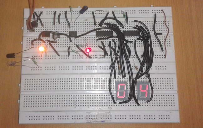
Object counters or product counters are important applications used in industries, shopping malls, etc. They count objects or products automatically and so reduce human efforts. In this tutorial we are going to design a simple object counter circuit without using any microcontroller.
Components
- LM358 IC - 1
- 555 timer IC -1
- Voltage Regulator 7805 -1
- 150 Ohm - 2
- CD4033 -2
- 10K resistor -2
- 100K resistor -1
- 10K POT -1
- 220uF capacitor -1
- IR sensors-1
- Bread board-1
- 9 Volt Battery -1
- Battery Connector-1
- LED -2
Circuit Diagram and Explanation
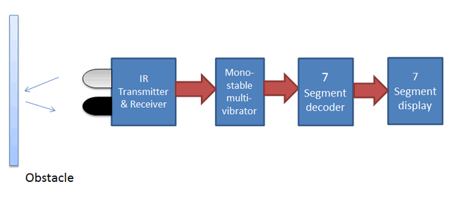
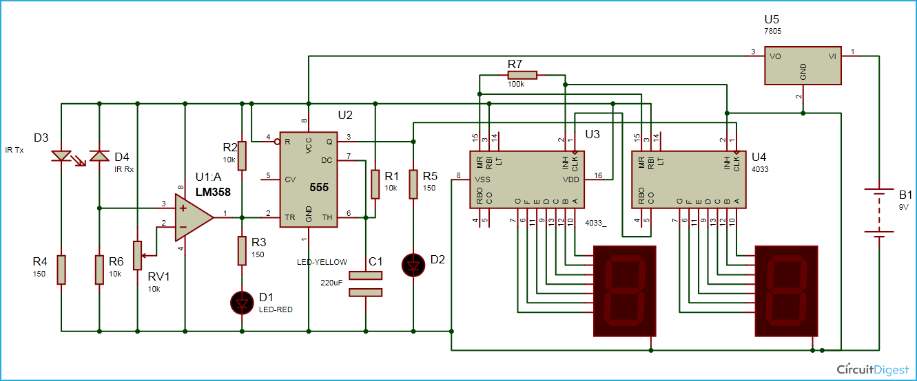
The circuit diagram of object counter is quite similar to my previous project (digital stopwatch circuit) but a little complex . In this circuit we have used a comparator (IC LM358) and IR transmitter and receiver pair for detecting a object. And then we have used a 555 timer IC to generate a pulse for triggering the seven segment decoder (CD4033) and two common cathode seven segment display units are connected with 7 segment decoder IC. 555 timer IC is configured in mono-stable mode for generating pulse. A LM7805 Voltage regulator is used for providing constant 5 volt power supply for the circuit. And a 9 volt battery used for powering the whole circuit.
Working
In this circuit we detects object by using IR sensor and comparator and then we applied output of comparator to mono-stable multi-vibrator. This mono-stable multi-vibrator generates a pulse of fix time period which can be set by using given formula.
T=1.1RC
In this circuit we have selected R1 is 10K and C1

After getting a pulse from 555 timer we applied this to clock pin of 7 segment decoder (U4) and then carry out signal (pin 5) to clock pin of another 7segment decoder (U3). After getting pulse from 555 timer 7 segment counter changes number value of segment display. and when number counting reaches at 10 in U4 decoder then it sends carry out signal or pulse to seconds 7segment decoder (U3) and then second display changes his number value. And this process repeats again. This object counter circuit can count 00-99.
Comments
Normally the range of IR LED is 2 meter, but it can be increased by using Lens. Video is the proof of its proper working, our all the projects are properly tested.
Hi I want to ask you that how can we add one more seven segment display to increase range upto 999
yes you can add third seven segment for displaying number till 999. you will need one more 4033 ic and a seven segment.
and connect seven segment to 4033 ic as shown in circuit.
here you need to connect CO pin of U3 ic to new 4033's clock(clk) pin.
if i cannot find the ic 4033, can i replace it with the ic 4026 and how should i connect
does the used of the dei instead of the rbi affect the circuit operation
yes, connect det as rbi.
Is there any coding in the project?
i assembled the curcuit as the cicuit diagram shows, using two Hcf4026 Ic. no infrared detected and its stuck at 08 on the displays. i really need your help xoz its my project
Take a look at this Circuit and try to understand the interfacing of IC 4026 with Common cathode seven segment and 555. Try with single seven segment first, and then multiplex the other one, and let us know the results with single IC.
Could someone please show me how to put this onto a stripboard?
DOES THE CIRCUIT DIAGRAM WORK
@Dez: All the circuits on the site are perfectly tested and working.
The infrared sensor worked perfectly. And it counted with one 7 segment using 4026 circuit diagram maddy availed. Thanks
Will only change the timing of the tripple five for effective counting
In which tool i can simulate this above circuit help me out in this as soon as possible
You can use Proteus to Simulate this circuit, use a Torch and LDR in Proteus, for IR pair. We have simulated similar one here in Video section: Reverse Car Parking Circuit
Hi ,
Thanks for sharing this project , I'm building a project that requires comparing two IR counters , so I was wondering if it is possible to compare two CD4033 outputs through an IC7485 or a similar comparator ? Or if you could suggest another idea of doing so , that would help a lot .Thank you in advance :)
hlw bro....i have made this circuit bt without tuch negative wire it dose not work. why this problem face??? please give me salution..
My circuit didnt run and pz send proper circuit daigram for beginners
hey this project is awsome, but can we decrement the counter as it is incrementing also if we want to decrement what we will doo pleasee help me i am stuck :(
dis crkt is not working . plz send me the correct circuit ASAP ..as i am fully dependent on ur site for my project and i have to present it on 14th may ..
@Niahat @aqsa nisar @ devang: Circuit is correct and working properly, please check your circuit twice and adjust the variable resistors properly.
Hey,
I have assembled this circuit, but it is not working properly. The IR receiver/detector pairs are working perfectly and so are the 7 segment displays. But whenever an object passes, the display is does not increment the number. Could you help me out?
Please respond as soon as possible, because this is for my project and I have no time left.
Yours sincerely.
Take a look at this Circuit and try to understand the interfacing of IC 4026 with Common cathode seven segment and 555. Try with single seven segment first, and then multiplex the other one
hey! please tell me the name of that 2 Ics is CD 4026 or not?
Good day, is there any way that this circuit can also counts down? Can you please show me the circuit how. Thank you.
You can do this using Microcontroller, check this circuit: Automatic Room Light Controller with Bidirectional Visitor Counter
sir I simulated this circuit diagram in proteous but the problem i,m facing is that it starts counting start from 01 and goes on while i want that it should start from 00 please help i,m waiting for your reply
This circuit looks awesome. But I want to decreament the count when an object is taken in opposite direction by adding another it ir sensor. Can u help me with this?
Check this one: Bidirectional Visitor Counter
plzzz send mi full component list
hello...
is there any extra connection in between 4033 and ssd....
extra resistors are used as shown video....
plz tell me the full description of ckt diagram..
Did you checked components and circuit diagram.
It seems that your using multiple 10k resistor and see list of components in that 10k resistor are only 2
Is there any specific type of IR receiver? If I am going to buy one, do I just ask for an IR receiver?
where should i connect the common pin(3,8) of the seven segment display??
helllo...
not getting output yar...
plz post the correct ckt diagram....
is their any one got the solution ...plz post it..
first part working properly i.e. it sense the object not count them....
__/\__
check your connections with 4033 ICs.
Can I ask sir if what would be the best replacement of cd 4033 if this circuit is not available? Thank u
You can use IC 4026, check the 7 segment interfacing with it here: 7 Segment Counter using IC 555 and IC 4026
Should I use a photodiode or a phototransistor?
Can I still used the diagram even if my ic is 4026?
Sir what if I wanna put a switch that would set the count back to 00. What pin should I place it?
Why is the LED on ON when no object is in front and goes OFF when an object passes by? Isn't the LED suppose to light only if the photodiode activates from the bounced IR (when an obstacle is present)?
What can i use to replace CD4033 for this circuit?
Can I still use this circuit if I used that replacement instead of the CD4033?
Please check all the comments above before asking, your question might have answered already.
Does the infrared pair need to be close to each other?
Hi sir,
Would I be able to get the codes for this circuit?
Hi I wanna ask is it possible that the IR sensor can detect black and white colour? Cause my project is doing black colour for player 1 and white colour for player 2 and if IR sensor detect black colour add 1 mark for player 1 and vice versa.
IR sensor cant detect colors, you should use Color sensor with some microcontroller or use IR remote with Microcontroller to get different function on different button press.
Hello... I want a help... I want to apply this project on PCB... Can you give me the PCB circuit diagram of this circuit... I really need help... I'll be grateful to you
Can u tell me plz the value of Pot ?
Hi this circuit can add down counting or up and down counter thanks
can we use 4017 in place of 4033
can i use IR transmitter and receiver in front of each other as I want to make a tachometer.
Hi
Please help
For this ckt using microcontroller with LCD interface .output of ic555 conected to the microcontroller then what happen ?
It can work properly ?
Please reply
hi i ask a question did project has code or not?
I am doing this project on PCB bt the routing process finishes only till 95 %, i connot proceed further help me out
As cd4033 isn't available in the market can you please suggest a replacement.
we only get common anode 7 segment displays (and IC 9447 decoder). Can u tell me the changes to the circuit?
Hi,
After looking at the circuit, what is the need for the 100K resistor which connects the MR and the INH to ground? Can't seem to work this out.
Thanks
Hi.
How can we add a reset button to reset the circuit. and can we convert the circuit into a bi-directional counter??
Revert back ASAP
is this circuit really works? is this circuit is simulated and tested
do we need to give supply to the 7 segment display where ???
and also what to do with cc connection in the display
sir .
if object 1st is detected bye the sensor than diaplay on the segment will be it count by 0--to---1
lets this object again come in reverse direction than what will be the count. Is it bye 1--to--0 ?????
i dont know how are these 7 segment display are connected ...
hi, thanks for sharing
if i wanted to reset the count to zero, what should i do??
ps: the reset signal is from a 60-seconds timer circuit
many thanks
Hello sir i am making this circuit for my project. The circuit in the video seems to be different from the proteus circuit diagram. I have implemented it and my ir sensor is working too. But the count value on 7 segment does not change from 00 please help me.
Hi guys. I dont know if you will reply but i really need your help. The circuit is all working and the output display is incrementing but not in proper way. My output doesnt show 00-99 instead it shows any number. It counts normally when it detects an object but it also counts when I releases the object. Hope you will reply
insted of 4033 ic, what ic I may use in this ckt
Hey i properly build the circuit but counting is no no increment
is there any component in circuit that has been grounded ,,,please tell which component or resistor or any....etc................................then whats the need of 10k pot ,wheres it in the circuit
How will you add a reset function? Thanks
How i make digital clock via seven segment .....
To make a digital clock you would need a microcontroller like arduino. Refer the below links to know how to build a digital clock using arduino.
https://circuitdigest.com/microcontroller-projects/arduino-alarm-clock
how to make 0 to 15 down counter project...???
This is awesome! Is there a circuit diagram for the numbers to count up and down without using a microcontroller or arduino. Plz replay ASAP.
i have a problem Please help!!!
all lights are on of my 7 segment.....
it is not counting object!
Hey, may i ask questions? Why my ir sensor nit function while construct at breadboard?
it doesnt work
Hi,how i can find the pair IR TX and IR RX on proteus and I am a beginner btw


hey,what is the maximum distance the two sensors can be kept apart?and is this circuit working properly?