
Today we are looking at one of the affordable frequency generator modules, that has ICL8038 as its heart. Surprisingly it is capable of generating 3 different types of waves which are Square, Sine, and Triangle. There is a lot about this module that needs to be discussed, so without further ado, let us jump into the explanation of the ICL8083 Module.
What is ICL8038?
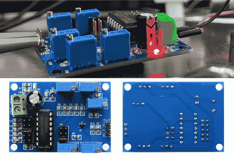
The ICL8038 is a simple and versatile waveform generator IC that can produce sine, square, and triangle waves with just a few external components. It’s great for generating signals in various applications, with a frequency range from 0.001Hz to 300kHz. You can easily adjust the frequency using resistors and capacitors, and even control frequency modulation with an external voltage. It's built to perform reliably across different temperatures and voltage ranges, making it a practical choice for signal generation. The image below shows the clear image of the ICL8038 Module.
Features of ICL8038
Low frequency drift with temperature: 250 ppm/°C
Low distortion (sine wave output): 1%
High linearity (triangle wave output): 0.1%
Frequency range: 0.001Hz to 300kHz
Adjustable duty cycle: 2% to 98%
Supports high-level outputs from TTL to 28V
Outputs sine, square, and triangle waves simultaneously
Specification of ICL8038 Frequency Generator Module
Below, you can see the general specifications of the ICL8038 module.
| Parameter | Symbol | Limits | Unit | ||
| Min | Typical | Max | |||
| Module Supply Voltage | Vss | 10 | 12 | 30 | V |
| Module Current | Is | - | 12 | 20 | mA |
| Output Frequency | Fo | 0.001 | 10 - 300K | 480K | Hz |
| Duty Cycle | - | 3 | - | 90 | % |
| Operating Temperature | To | -50 | - | 150 | °C |
| Storing Temperature | Ts | -65 | - | 150 | °C |
The table above is for beginners. If you are looking for more advanced details, refer to the official ICL8038 Datasheet.
The most important factor here is the input voltage. I recommend using a constant input voltage if you expect a consistent waveform, as the output waveform changes its properties such as frequency and amplitude, whenever the input voltage fluctuates.
To be precise, the data sheet itself states the maximum frequency of 300 kHz but this module can pump up to 480 kHz which under testing produces unstable frequency with lower amplitude than regular.
Hardware Overview
Let's take a deeper look at the hardware itself. Given its complexity, we will break down the details into multiple subtopics.
We'll begin with the pinouts.
Pinouts of ICL8038 Module
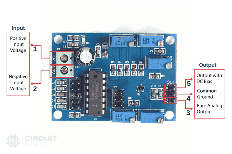
In the ICL8038 module, the pinouts are straightforward. You need to power it, and the desired waveform of your chosen configuration can be obtained from the output. Below, you can see the pinout image and the table that describes the pinouts of the ICL8038 module.
| Pin No | Pin Name | Type | Description |
| 1 | VCC | Power | Module Supply Voltage |
| 2 | GND | Power | Ground Connection Pin |
| 3 | AG | Analog Output | The output pin that's best suited for receiving the sine and triangle waves. |
| 4 | G | Power | Ground Connection Pin |
| 5 | DC | Digital Output | The output pin that's best suited for receiving the Square waves. |
The supported input voltage range is approximately 10 to 30V maximum. However, 30V is not recommended as it will eventually increase the operating temperature. An optimum of 12V is suggested for better operation.
The output can be drawn in two forms: one as a pure analog wave and the other as a DC-biased voltage. Each has its unique advantage. Analog output is best suited for sine wave output, while DC output is best suited for triangle and square wave outputs.
Next, we will continue with the configurations.
Configurations available in ICL8038 Module
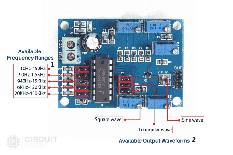
Typically, there are two configurations available in the ICL8038 module: frequency range selection and waveform type selection. The image below shows the exact shunt jumper positions that need to be adjusted to select the correct configuration, along with a small table describing the available configurations.
Part No | Part Name | Description |
1 | 5 way - Shunt Jumper | For Configuring Frequency Range |
2 | 3 way - Shunt Jumper | Configuring Output Wave Type |
One thing to remember is that selecting the correct frequency range is important to achieve the desired output. Ideally, try to position the desired frequency in the middle of the range to allow smooth adjustments and ensure a stable output. For example, if you need 100Hz, a range of 10Hz to 450 Hz is suitable. If you need 100kHz, a range of 6kHz to 120kHz is recommended.
Finally let's look at the controls available to tune the wave form.
Controls Available in ICL8038 Module
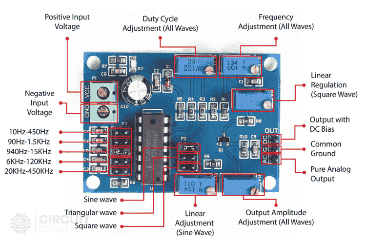
This module has all the major tuning options, allowing us to easily modify the signal’s waveform. Below, you can see the part-marking image of all the components that assist in tuning the signal, along with a table representing each control option and its scope of operation.
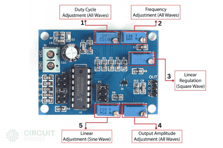
Part No | Part Type | Controllable Waveform | Description |
1 | Trimmer Potentiometer | All | Duty Cycle Adjustment |
2 | All | Frequency Adjustment | |
3 | Square Wave | Linear Regulation | |
4 | All | Output Amplitude Adjustment | |
5 | Sine Wave | Linear Adjustment |
Here is some information I would like to add,
Duty cycle adjustment, frequency adjustment, and amplitude adjustment are common for all types of waveforms. However, linear regulation or adjustment is an additional feature for square and sine waves.
Except for amplitude adjustment, every other control has some influence on the signal's frequency. So, be cautious when setting the correct frequency for your application.
Schematics of ICL8038 Module
Finally, here is the schematic, which is essential for understanding, recreating, or modifying the ICL8038 module. Below is the complete schematic diagram of the module.
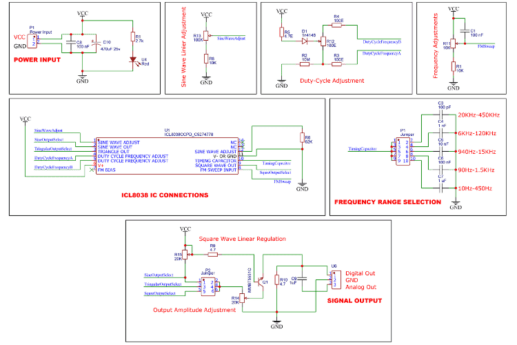
Starting with the Power Section, the input voltage is passed directly to the circuit without any regulation. Before reaching the circuit, the voltage goes through two filter capacitors to prevent surges. Additionally, there's a power indicator LED near the input.
You can also adjust the frequency of the output waveform by altering the input voltage at the FM Sweep Pin of the ICL8038. This changes the charge and discharge timing of the capacitor, affecting the output frequency.
There are two separate circuits to adjust the waveform: one for sine wave linearity and another for duty cycle adjustment. Specifically, you use the R13 potentiometer to fine-tune the linearity of the sine wave and the R12 potentiometer to adjust the duty cycle of all waveforms.
Finally, we have the Output Section. The module generates three waveforms simultaneously (sine, square, and triangle). You can select the desired waveform using a shunt jumper(P2). The selected waveform is amplified by a general-purpose NPN transistor (Q1). The amplitude can also be adjusted using the R14 potentiometer. Additionally, the R15 potentiometer, connected to the base, is used to adjust the linearity of the square wave that doesn't affect other waveforms..
For the outputs, the module provides two options—AC and DC. Typically, DC output is preferred for square and triangle waveforms, while AC output is more suitable for sine waveforms. You can choose the appropriate output based on the selected waveform and your specific needs.
Next Let's see about the Controlling and its Relative Output.
Guide Tuning the Output Signal
Here, I will show all the configuration and tuning options along with the output recorded from the oscilloscope. As we know, there are three different waveforms, and among these, there are four different controls, except for the triangle waveform, which has three controls. Starting with the sine waveform.
Remember: Every GIF has two signals, one in yellow and another in blue. The yellow signal is the DC output, while the blue signal is the analog output. All footage is taken while providing 12V to the ICL8083 module. The GIFs are recorded while rotating the respective potentiometer.
SineWave - Amplitude Adjustment
Below is the waveform captured while adjusting the amplitude trimmer potentiometer. As you can see, we get an approximate output range of 320 mV to 5.12 V with an input voltage of 12 V. Although the DC output (yellow wave) appears similar to the AC wave, the key difference is that the analog output has a proper offset over the signal period, while the DC output is most likely a true DC output.
Therefore, it is recommended to use the analog output for the sine wave.
SineWave - Frequency Adjustment
It is generally observed that adjusting the potentiometer changes the frequency within the selected range. However, if you turn the potentiometer to either end, the output will be null. It is better to keep the potentiometer in the middle position. Additionally, the frequency is not stable at the ends of the potentiometer's range.
SineWave - DutyCycle Adjustment
There is generally no need for duty cycle adjustment in a sine wave. However, here is what happens when you adjust the duty cycle while in sine wave configuration.
Ensure that the duty cycle is set to approximately 50% to maintain a proper sine wave.
SineWave - Linearity Adjustment
In the sine wave configuration, adjusting the linearity allows you to modify the timing between the positive and negative cycles.
In most cases, it should be kept close to 50%. Only under special conditions would you need to adjust the linearity to either end.
TriangleWave - Amplitude Adjustment
Now we switched to the triangle wave form output. Here Amplitude adjustment is as usual. And similar ranges of voltage like sine wave has observed.
In the GIF above, you can clearly see that the DC output (yellow wave) provides the best triangle waveform. Therefore, it is best to use the digital bias output for the triangle wave.
TriangleWave - Frequency Adjustment
As with the sine wave, adjusting the frequency of the triangle wave produces similar results.
Also, remember to avoid tweaking the ends of the potentiometer, as the output will be null at those extremes.
TriangleWave - DutyCycle Adjustment
An interesting observation is that while adjusting the duty cycle in the triangle wave configuration, you can obtain two additional waveforms: the positive ramp and negative ramp.
In the GIF above, you can see three types of waveforms, the sawtooth negative ramp, the triangle wave, and the sawtooth positive ramp.
SquareWave - Amplitude Adjustment
In the square wave configuration, the DC output (yellow wave) provides a more appropriate square waveform. Therefore, it is suitable to choose the DC output for the square wave.
Regarding the output voltage range, we successfully achieved 320 mV to 7.6 V, which is slightly higher than the sine wave. As usual, a 12V input voltage is given to the module.
SquareWave - Frequency Adjustment
Similar to the other waveforms, the result is the same when adjusting the frequency of the signal.
SquareWave - DutyCycle Adjustment
Here, I have a slight disappointment because, as shown Below GIF video, the output signal does not cover the duty cycle range specified in the datasheet of the ICL8038 IC. which is 2% to 98%.
So, some fine-tuning of the circuit might be necessary.
SquareWave - Linearity Adjustment
While adjusting the linearity of the square wave signal, we observe that it only affects the amplitude of the signal. The purpose of this adjustment is unclear, as we already have a separate potentiometer for adjusting the amplitude.
Application of ICL8038 Frequency Generator Module
Due to its ability to generate multiple types of waveforms, there are a variety of applications. Let's explore a few,
Signal Generation
Used as a function generator to create sine, square, triangle, sawtooth, and pulse waveforms for testing and troubleshooting circuits.Modulation System
Helps generate carrier signals for Amplitude Modulation (AM) and Frequency Modulation (FM) systems. It is also useful for testing communication circuits.Audio Testing
Useful for generating audio signals to test speakers, amplifiers, and audio processing circuits.Oscillator Circuits
Acts as a tunable oscillator in electronic circuits that require a variable frequency source.Waveform Analysis
Assists in simulating and analyzing different types of waveforms in research, teaching, and laboratory setups.Pulse Width Modulation (PWM)
With adjustable duty cycles, it can be used in applications requiring PWM control, such as motor control or dimming LEDs.


Nice features, but I sure miss looking at 50 dB SNR analog waveforms. The noise and sine THD is excessive.