Hello everyone :)
Any chances somebody can spare few minutes and look at a simple diagram i'm struggling with ?
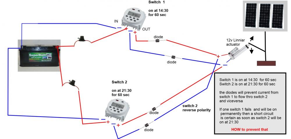
Basically I would like to use two diffrent timer switches to power a 12v liniar actuator which will rotate a solar panel back and forth .
One switch will have the output polarity swapped so the actuator will move in aposit direction
the problem might accur if both timers will ( somehow ) be on at the same time - that will result in a short circuit , The diagram I have attached explains everything
If somebody can sugest a solution that will be much apreciatted !
I'm a newbie with very basic electronic knowledge
Thank you !

In reply to Thanks for your reply! by Iurie
Most relays can be connected in either of 2 configuration, NC (normally closed) or NO (normally open), so by wiring a relay in series with switch one in NC, power will only flow while the relay is energized, if power is cut, than the relay is de-energized cutting the circuit.....I think that may work, but I don't profess to be a pro, I found your post looking for help for my self.
Most relays can be connected in two configurations, NC (normally closed) or NO (normally open), so by connecting a relay in series with a switch in NC, current will only flow when the relay is energized, if the current is unplugged. relay de-energizes to break the circuit. .... I think this could work, but I don't claim to be a pro, just found your post looking for some help for myself.
If the relays are open will wind push the linear actuators? Will it overshoot from inertia or will you choose a good dead-band,
I would not recommend relays a linear actuator unless heaviliy-geared down with friction. When you short a motor it becomes a brake. This would require a 3 position switch Fwd-Short-Rev. with floating contacts in between each state.
This is best done with complementary full bridge FETs in an Arduino CNC shield or similar. A stepper-motor driver can be used if the brake position reduces the drive current or duty cycle so that both actuators are active such as in the toy linear servos with current controlled acceleration, velocity limits and Position error control with your dual LED solar angle sensor. You want a large deadband so that power is not wasted dithering the tracking motors. This is why linear actuators unless hydraulic are not advised.
Hi there,
One way to prevent a short circuit if both timers are on at the same time is to use a DPDT relay. A DPDT relay has two sets of contacts, one that is normally open (NO) and one that is normally closed (NC). When the relay is energized, the NO contacts close and the NC contacts open.
You can wire the relay so that the output of one timer is connected to the NO contact and the output of the other timer is connected to the NC contact. The actuator is then connected to the common terminal of the relay.
When only one timer is on, the corresponding contact will close and the actuator will move in the desired direction. When both timers are on, both contacts will be open and the actuator will not move. This will prevent a short circuit.
Here is a diagram of how to wire a DPDT relay to prevent a short circuit:
[Diagram of DPDT relay wiring]
I hope this helps!


EagleFox
Joined December 30, 2021 3Thursday at 05:59 AM
Maybe connect a relay in series with switch one that is set to NC, or normally closed, if there is a short circuits, the relay will than be set to OPEN preventing the short?...Just bought 10 SDR-5V relays for $6-7...